This is the Worby Beaumont description ("Motor vehicle", 1900):
The position of the engine at the rear, where most of the passenger weight came, put an unnecessary load on the hind wheels, and for good steering too little on the front wheels. The Peugeot position for the engine is moreover inferior with respect to convenience of the driver.
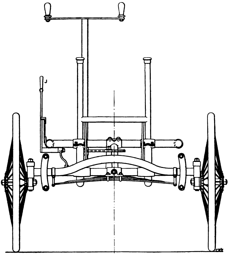
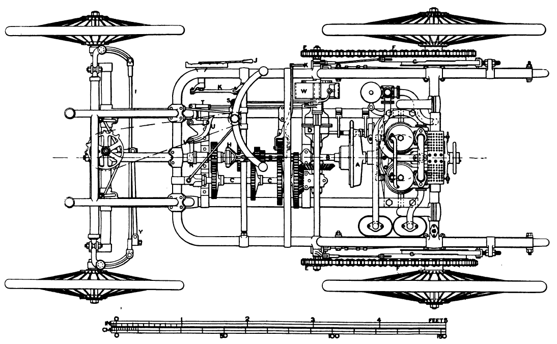
The under-frame of the Peugeot car is tubular and it has some important members at a lower level. The rear part is carried on long leaf springs, with range sufficient to allow them to straighten. The front is carried on one long cross spring. The upper and lower members of the under-frame form a truss the parts of which are maintained or braced by the pieces carrying the bearings of the clutch and countershafts. The fore-carriage gear differs in arrangement from those of other makers, though its essential features have been since embodied in some American electrical cars. A transverse member of the front of the frame is pivoted to the center bridle of the spring, the ends of which are connected to the main fore axle by cranked hangers.
At the extreme ends of the fore frame are two quadrants, against which the ends of the main axle rest, and are guided, leaving the axle free to move up and down angularly, by a lift from either wheel, without affecting the frame.
The motor of the date of this carriage was the V-type Daimler. The carburetor used on some of the cars was of the Daimler surface type with slight modifications.
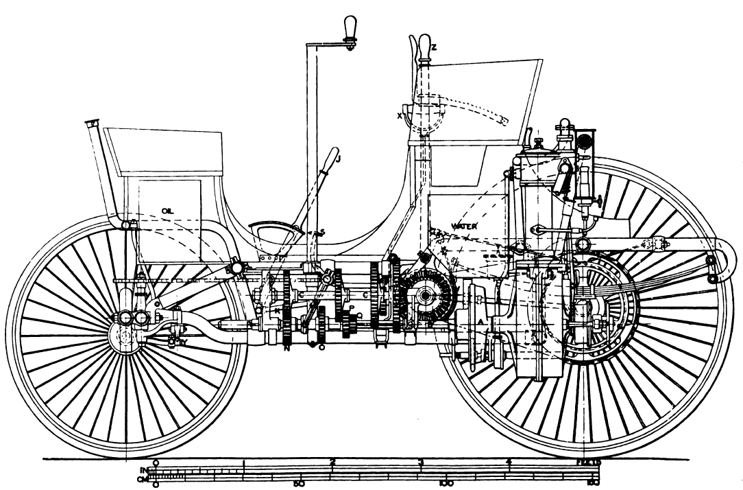
The power of the engine was transmitted by means of a clutch A to a square clutch shaft B, carrying four pinions of different diameter, which geared selectively with four wheels on the second motion shaft c, for four speeds, and with one separate wheel for reversing. At the rear end of the second motion shaft was a bevel pinion gearing, with a bevel wheel on the transverse shaft, which carried the differential gear D, and at its ends, the pitch chain pinions see, which communicated motion to the driving wheels by chains f on sprocket wheels on the driver limbs, these sprocket wheels also carrying brake pulleys, on which the brake straps g g acted, and were actuated by the lever Z.
At the front end of the clutch spindle was a sleeve r, in which was a spring acting against a collar for pressing the clutch into gear. For throwing this clutch out of gear the pedal s was used. By depressing this pedal the rod was pulled, and the end of this was connected to a bell crank lever. On the end of one arm of the latter was carried a smaller roller acting against a bent lever u, pivoted at v, the outer end of the bent lever being connected to the sleeve on the end of the clutch shaft. By this circuitous path the clutch was put out of gear or allowed to go into action.
By further depression of the pedal S, a brake W on the transverse shaft is applied. For reversing, the speed change lever was set between the first and B second speed notches, and then the handle x put forward. This shifted an independent spur wheel, movable mounted on a bracket (as indicated in the center of the plan, and in the elevation), and put it into gear with a pinion on the clutch shaft, and a wheel on the second motion shaft. The reverse motion was thus given to the latter. Of course the clutch pedal was depressed when any of these changes were made.