William Worby Beaumont (” Motor vehicles and motors”, 1900):
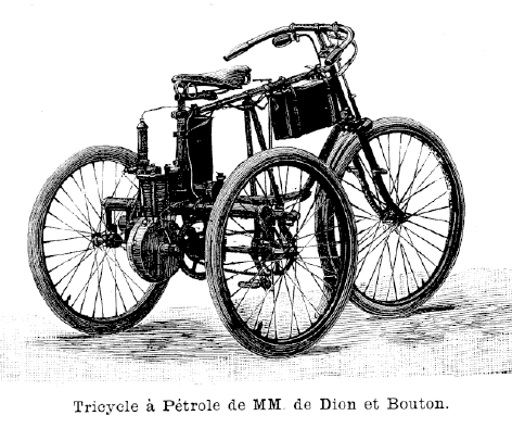
“In 1896, the Dion tricycle ran in the Paris-Marseilles race, making an average speed over the whole distance of 14,8 miles per hour, and in the Paris-Bordeaux race, 1899, another of the same make accomplished 28,1 miles per hour, the first being fitted with a 1 HP. Dion-Bouton, air-cooled Daimler motor, and the second with a 13 HP. motor of the same kind. Subsequently these motor tricycles were fitted with 2:25 HP motors, and some with a two-speed gear. They have become extremely popular machines, and very large numbers are in use, many of their owners accomplishing long journeys with regularity upon them.
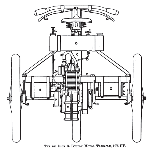
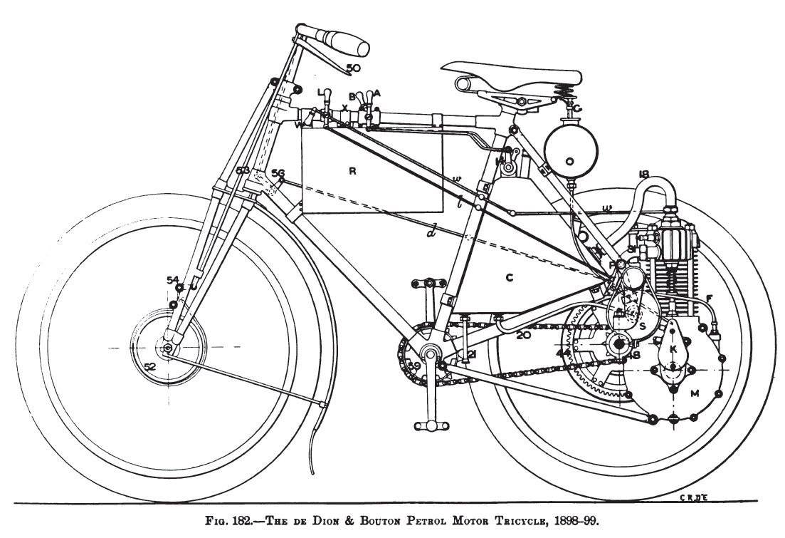
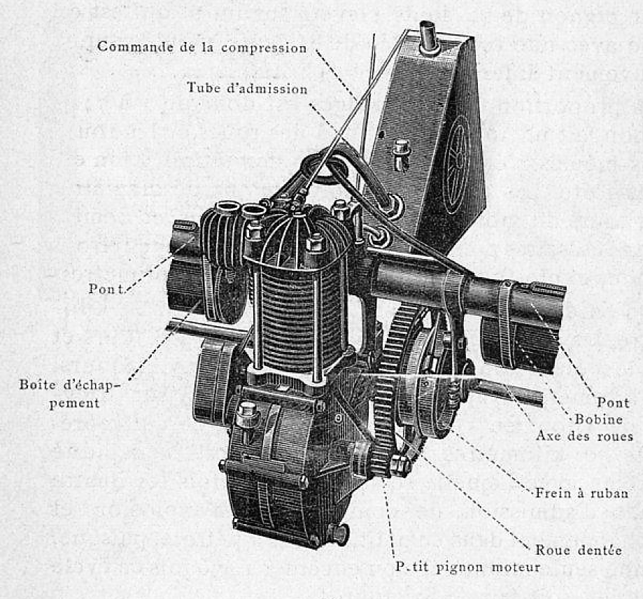
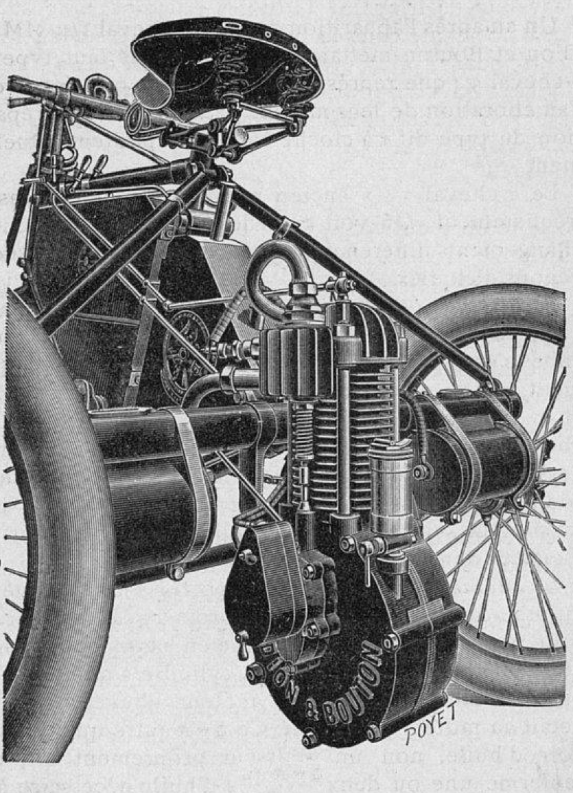
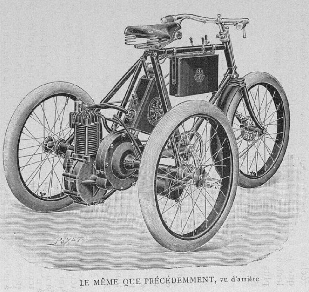
The pictures show a side and back elevation of a de Dion-Bouton tricycle of the 1898 type, fitted with a 1 3/4 nominal HP. motor.
The construction and design of the frame is similar to that of an ordinary tricycle, with the exception of the trussed form of fork which gives strength to what would be a weak structure for the purpose if built of simple tubes of the same weight. It will be seen that the motor is attached to the rear of the main axle, which it drives by single reduction gear. The motor is supplied with carbureted air from a vessel placed between the main pillar of the frame and the back.
The mixture is fired in the motor cylinder electrically, by spark at the points of an ignition plug, which receives current from a battery suspended from the top frame tube, and an induction coil carried on the bridge of the main axle.
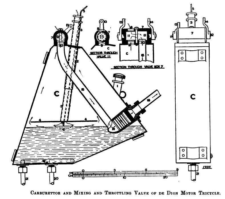
The carburetor c is so shaped as to fit between the saddle-post and back tubes of the diamond frame, to which it is attached by means of light clips. The details of construction are shown in the picture. It consists of a light box c of sheet brass, the lower portion of which forms the petrol reservoir, the spirit being introduced through the aperture 1. Inside the box at the top is brazed a tube 2, which forms the guide for a sliding tube 3, which is open at both ends. At the lower end of the tube 3 is soldered a flat metal plate 4, and through its length passes the wire 5 attached to a float 6, by means of which the level of the petrol is indicated.
To the top of the carburetor box are attached the air and carbureted air controlling valves. These are combined and form a cylindrical double valve 7, in the shell of which are three apertures 8, 9, 10, as seen in the details with Fig. 184. This double valve contains independent cylindrical valves 11, 12, which are operated by means of the lever handles a, b mounted on the top stay tube of the frame. These levers are connected by light rods to the lever arms 13, 14, on the valve spindles.
The two valves are of the same size, and nearly meet in the middle of the containing shell 7. A copper pipe 15 passes inside the box c from the aperture 10 in the double valve to the cone-shaped end of a chamber 16, in which is a copper cylinder 17 containing discs of wire gauze. To the end of the chamber 16 is connected the pipe 18 which leads to the admission chamber of the motor. At the bottom of the vessel, below the level of the petrol, is a pipe 19, to one end of which is connected a branch pipe 20, from the exhaust pipe 31 of the motor, while the other end has attached to it a downwardly projecting pipe 21, out of which the heated gases escape after passing round the pipe 19 within the carburetor.
The action of the apparatus is as follows: On each suction stroke of the motor a partial vacuum is formed within the box c, and consequently air rushes down the pipe 3, the height of which, above the surface of the spirit, is regulated by means of the float, and indicated by the wire 5, 6. Sweeping over the spirit, below the plate 4 and the wetted surfaces, the air becomes richly impregnated with hydro-carbon vapor, and the mixture thus formed passes out of the carburetor box through the aperture 9, regulated by the valve 11. At this point it mixes with pure air, entering at 8, the diluted mixture passing thence through the aperture 10, controlled by valve 12, and down the pipe 15 into the chamber 16.
Within this chamber is the gauze cylinder 17, which prevents the possibility of the vapor within the carburetor becoming ignited by a back fire in the motor. The mixture passes out of the chamber 16 by way of a pipe 18, which connects it to the admission pipe of the motor.
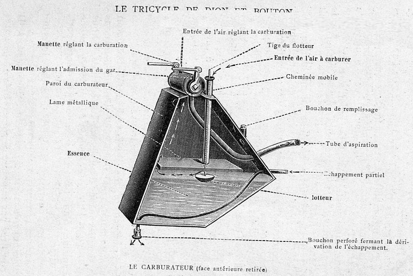
The pipe 19 at the bottom of the carburetor becomes heated by the passage through it of the exhaust gases, and by raising the temperature of the petrol causes it to be more readily vaporized. In very hot weather it is usual to disconnect the pipe 20 altogether, as the petrol vaporizes sufficiently readily without it. A small cock in the pipe would give a ready means of adjusting the supply of hot gases to the pipe within the carburetor, and save the trouble of disconnecting and leaving the pipe open.
The action of valve 11 may be described with reference to the diagram which shows the relative positions of the parts 8, 9 in the valve and in the valve case. It will be seen that as the lever 13 is moved towards the right, more air will be admitted at 8, and less carbureted air at 9. Movement of the arm in the opposite direction produces a contrary effect, so that with this valve and the valve 12 the quality and the quantity of the charge entering the motor cylinder are completely under control.
Thus, to recapitulate, it will have been seen that the suction by the motor piston, acting through the pipe 18, draws a supply of diluted carbureted air through pipe 15, the pure air having entered at 8, and the air which has been carbureted having entered at the top of the pipe 3, on its way to the surface of the petrol, and thence by the port 9 to the port 10.
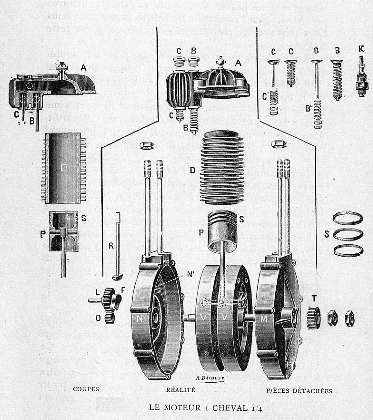
The motor m of the tricycle, which is seen in the pictures is of the vertical, single cylinder, Daimler type, originated by Messrs. de Dion & Bouton in 1895, and subsequently modified by many improvements in detail.
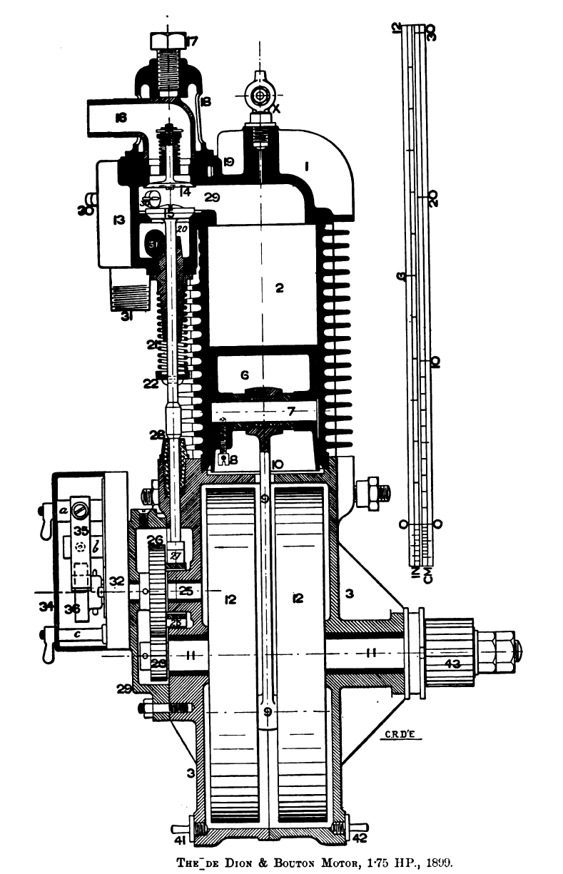
The pictures show a vertical section and an elevation of the latest type, developing 1 3/4 nominal HP. ; the actual B. HP. which the motor can give continuously being from 1,3 to 1.4. It is constructed in three principal parts : the cylinder head 1 and cylinder body 2, both of which are of cast iron, cooled by means of radiating ribs; and the crank case 3, which is an aluminum casting, divided along the central vertical plane, and bolted together, as seen clearly in the pictures. The joint between the cylinder head and body, and that between the body and crank case, are accurately turned and faced, and held by means of four long vertical studs 5, which are screwed into large bosses in the aluminum crank case.
The bore of the cylinder is 2§ in. = 67 mm., by 23 in. = 70 mm stroke. The piston 6 is of very light construction, and has three in piston rings. The cross-head pin 7 is held in bosses in the piston casting by means of the set screw 8. The connecting rod 9 is a steel forging of light H section, with brass bushed eyes at either end. The rod passes through a rectangular slot 10 in the crank case, through which oil from the lower part of the case is thrown up by the crank and connecting rod, and thus lubricates the cylinder. The slot 10 is not made of larger dimensions than those shown, in order that an excess of oil shall not reach the cylinder and piston. The crank on the driving shaft 11 is formed by means of a fixed pin joining the two fly-wheel discs 12, 12, which are enclosed within the crank case.
The valve chamber 13, which contains the admission and exhaust valves, is cast with the cylinder head as close as possible to the cylinder wall, so as to minimize the port space leading to the combustion chamber.
The valves are placed in a vertical line : the admission valve 14 at the top, and the exhaust valve 15 below. The admission valve is of the usual spring-held type. The seat and valve-stem guide are formed by a separate removable piece, into which fits the admission chamber pipe 16, the whole being held together by pressure of the set screw 17 at the top of the bell-shaped cover 18. This cover is held in place by a form of bayonet joint, the cover having at its lower end three projections, which engage with an interrupted annular groove 19, so that when the set screw 17 is tightened, the cover is held firmly in place.
The exhaust valve 15 is held on its seat above the chamber 20 by pressure of the spring 21, the lower end of which is carried by a cup 22 held by a small cotter in the valve spindle, which is guided by a long bush screwed into the bottom of the valve chamber. The valve is made of steel, which seems to be the best material for these small things, and works well on the cast-iron seat. No real trouble attends these valves, but possibly nickel steel would best suit the work.
The valve is lifted in the usual way by means of an annular cam 33, projecting from the inside of a spur wheel 26 on the spindle 25. This wheel gears with a pinion on one end of the crank shaft, the cam being thus revolved at half the speed of the motor. The cam bears against a sector-shaped head 27, at the lower end of the vertical rod 28, the upper end of which is enlarged where it meets the exhaust-valve spindle. The whole of the cam gear is enclosed in a box filled with oil, formed by one side of the crank case, and the cover 29 held by studs, as seen in the pictures.
The motor works on the usual four-stroke cycles. On the first down stroke the admission valve opens and allows the charge to pass from the carburetor to the admission-chamber pipe 16, Figs. 185 and 186. On the following up stroke the admission valve closes, and the charge is compressed into the combustion chamber and port space 29, and fired by the passage of an electric spark between the points of the sparking plug 30.
The piston next performs the working stroke, at the completion of which the exhaust valve is lifted by means of the cam 23, and the products of combustion pass into the chamber 20, and thence by way of pipe 31 to the exhaust silencer s, Figs. 182 and 183, a very small portion being diverted to aid the vaporization of the petrol in the carburetor, as previously described.
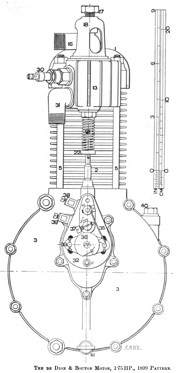
The variation of the point in the stroke, at which the clergy is fired in the motor cylinder, is effected by means of the adjustable contact maker k, which is mounted at the end of the second motion spindle 25, and controlled by means of the small hand lever l, connected by the rod b, Figs. 182, 188, to a lever arm on the sleeve L’ which is free to turn on one end of the spindle p, carried in bearings brazed on the axle-bridge tube. The motion of the sleeve L’ is transmitted to the contact device by means of the lever arm and rod k.
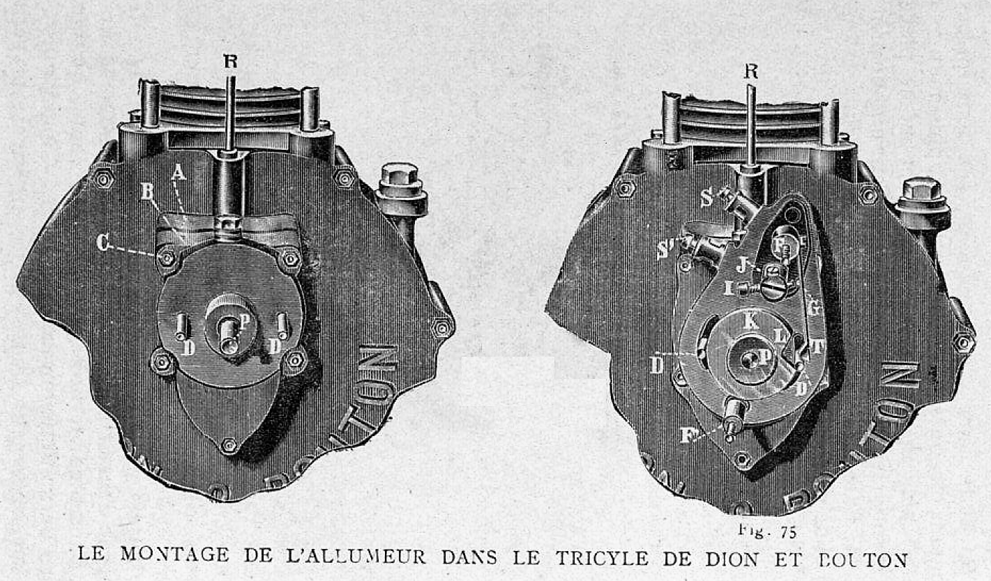
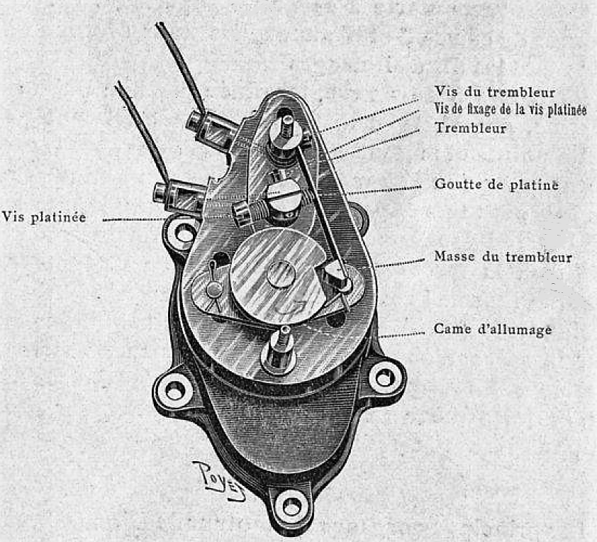
The contact maker consists of an adjustable vulcanite disc 32, which is held against the cover 29 of the cam chamber, by means of the plate and the studs 33, which pass through slot holes in the vulcanite. On the vulcanite disc are mounted three brass standards a, b, c, the upper and lower of which a, c have their ends turned down and screwed. Over these ends is slipped the aluminum cover 34, enclosing the contact making device k.
At one side of the standard a is fixed a steel spring 35, on the end of which is a projecting head which bears against a steel disc 36 fixed to the extremity of the spindle 25, and on the circumference is cut a notch d.
The rotation of the disc 36 causes the head of the spring once every two revolutions of the motor to fall into the notch d, thus allowing the spring to press against the platinum tip of a set screw 37 in the standard b. The standards a, b are in electrical connection with the binding screws 38, 39 on the side of the vulcanite base 32, there being connected one to a battery terminal and one to an end of the primary circuit of the induction coil z, Figs. 183 and 189, so that whenever the head of the spring 35 falls into the notch d, the primary circuit is completed through the spring and screw 37, and the induced secondary current is discharged between the points of the sparking plug 30.
The lubricant is supplied to the crank case of the motor, through the aperture 40, closed by a screw plug, and withdrawn through the apertures 41, 42, closed by thumbscrew plugs, as seen in Figs. 185 and 186. A special form of cylindrical oil tank o is usually attached to the back stays of the tricycle frame ; it is divided internally into two compartments, the larger of which contains a reserve supply of petrol, which may be fed to the carburetor box c, through the pipe D the supply being controlled by a valve operated by the hand wheel E.
At the other end of the tank o is a smaller compartment, containing a supply of lubricating oil for the crank case, to which it is connected by the pipe f, the oil being injected by the driver, by means of small pump operated by the plunger g, without the necessity of his leaving his seat.
The motor drives the rear axle of the tricycle by means of the machine cut steel pinion 43, which gears with the bronze spur wheel 44, bolted to the case of the differential gear on the driving axle 45, which runs in ball bearings 46, 47, 48, 49, attached to brackets brazed to the bridge tube of the tricycle frame.
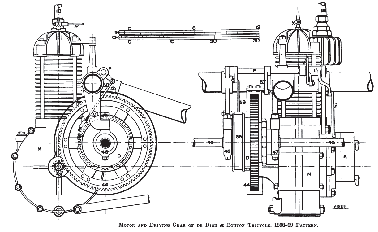
The engravings show the gear as made in 1899, but the partial gear protection shown is that of the 1898 pattern. This gearing is now completely covered in by an aluminum case similar to that of the crank. To some recent tricycles a two-speed gear of one or other of several patterns is fitted, as a means of hill climbing with less pedal work, and also as a means of preventing the stoppage of the motor when it falls below a certain minimum speed. Reference to these gears will be made hereafter.
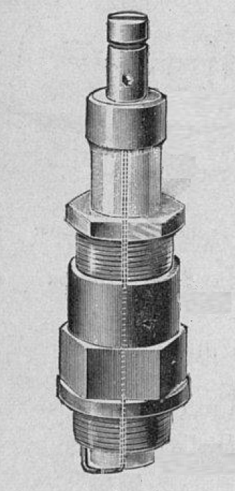
Electric ignition apparatus
The electrical outfit for firing the charge in the motor cylinder is shown diagrammatically by the picture:
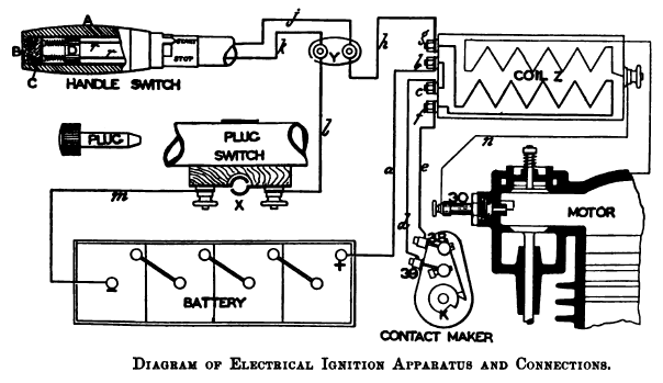
It consists of a four-cell primary battery carried in the case r which is slung from the top stay of the tricycle frame. This battery is of the dry cell type, and has a working life of about 300 hours. One terminal of the battery is connected by wire a to the terminal b at one end of the induction coil z. This terminal is cross connected to a similar one c, which is connected through the contact-making device k, by wires d, e, to one end of the primary circuit of the induction coil, at terminal f; the other end of this circuit at terminal g is connected by wire h to one of two binding screws, mounted upon the vulcanite base y at the top of the tricycle head. These terminals are connected by wires j, k, which pass through the tubular handle bar to the handle switch.
This switch operates in the following manner: the horn handle a is free on the end of the handle bar, and has at its inner end a metallic sleeve and index, which may be set to positions marked start and stop on the handle bar. Inside the handle bar at its outer end, and attached to the handle a, is a vulcanite piece b, upon which is fixed a metal strip c. This strip, when the handle is turned to the start position, makes contact between the ends of the spring-controlled rods r r, which pass through the vulcanite piece d, and to which are connected the wires j, k from the terminals on the block y.
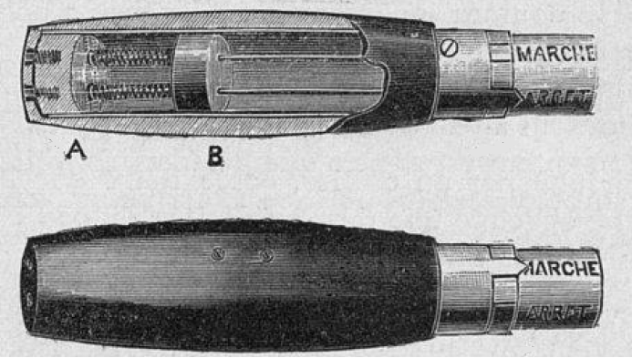
When the handle is revolved to the “stop ” position, the metal strip c takes up a position centrally between the ends of the rods r r, so that the circuit is broken. From this switch, when the circuit is completed, the current flows by way of wire l through the plug switch x which is mounted om the top stay of the tricycle frame, and thence by wire m to the negative terminal of the battery.
The plug switch x enables the rider, when the machine is left unattended, to effectually break the electrical circuit, so that the motor cannot be started accidentally or by interference. The positive secondary terminal of the coil z is connected by wire n to the insulated conductor within the sparking plug 30. The other or negative end of the high tension part of the coil z is connected, as a convenient place, to one of the coil carriers, and thus the circuit is completed.
The tricycle is controlled by means of two band brakes which are operated by the levers 50, 51 pivoted below the handle-bar on either side of the head. The lever 50 operates the band brake 52 through the rod 53 and bell crank 54. The lever 51 operates the band brake bb on the exterior of the differential gear box d on the driving axle. The movement of the hand lever 51 is communicated through the bell crank 56 and rod d to the lever 57, Fig. 188, on the spindle p, a second lever arm, on the end of which is connected by the adjustable rod 58, to one end of the band 55 of the brake, the other end of which is attached to the bracket of the axle bearing.
The relief pressure cock x at the top of the motor cylinder is controlled by the driver by means of the handle w actuating the jointed rotative rod w. To prevent the noise made by the escape from this cock when opened from fighting horses, it should be coupled up in a small pipe to the silencer s.
The motor is started by the rider, by pedaling in the usual manner, the relief pressure cock being first opened. When the motor is working properly, the cock x is closed, and pedaling stopped ; the motion imparted to the chain by the sprocket pinion on the driving axle causing the silent pawl clutch 59 on the crank spindle to be put out of gear.