Baudry de Saunier, "L'Automobile théorique et pratique"
"Patent No. 9907, April 20, 1897.-Oil engines, P. G. A. Peugeot.
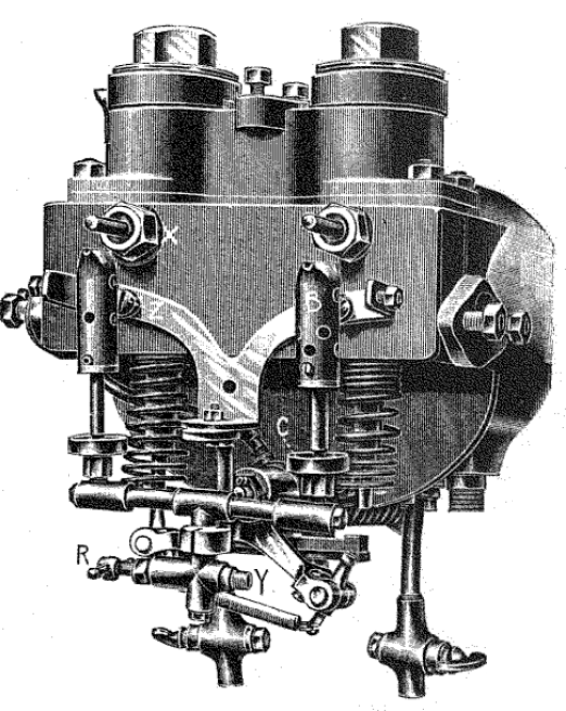
The engine has two cylinders placed side by side, their pistons being coupled by connecting rods a b to cranks, between which is mounted a cylindrical cam c concentric with the crankshaft, and having a peripheral reverse l lookup spiral cam groove for effecting the distribution of explosive mixture to the two cylinders. The valve chambers of the two cylinders may either be quite separate or be contained in one casting comprising the two compression chambers and the two chambers for the admission and exhaust valves.
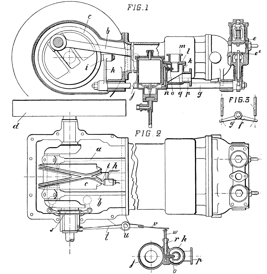
The admission valves e are self-opening, whilst the exhaust valves e' are opened alternately, each once for every two revolutions, by a rock shaft g operated through an arm h and slide block i by the reversed spiral cam groove, the rock shaft y having arms f, which act directly upon the valve spindles. The carburetor comprises an oil regulating chamber j containing a float acting on a supply valve beneath it through the medium of levers whereby when the float falls the valve is opened so as to maintain a constant level in the chamber j, and also an oil spraying and carbureting chamber k alongside the supply regulating chamber, and having a cover l and an open mouth m for the admission of air. The oil passes from the lower part of the regulating chamber through a channel n to a nozzle o having one or more orifices, and leading into the air inlet passage of the carbureting chamber, from which nozzle the oil in projected in a fine stream across the said passage, so that it meets at right angles the current of air drawn there through by the in stroke of the piston, the oil becoming pulverized by the shock and intimately mixed with the air, which may or may not have been previously heated. At the lower part of the carbureting chamber is a division q formed of wire gauze inclined at about 450, through which the carbureted air must pass, and upon which any oil not immediately taken up by the air must fall, so that the air in traversing the meshes of the gauze will become saturated with oil before pissing from the carbureting chamber to the admission valve chambers of the engine to which the outlet p of the carbureting chamber is connected. The oil chamber n leading to the spraying nozzle is controlled by a, valve r, which is opened by a spring w, and closed by the action of a centrifugal governor upon the engine shaft within the crank chamber, the action of the governor being transmitted through a collar s sliding on the shaft and connected by a rod sliding through the journal bearing with a lever t pivoted at u, and having a spring arm v which acts directly upon the stem of the valve r, so that when the governor balls fly out the valve is closed, and interrupts the passage of the oil to the spraying nozzle, so that the engine draws in only air, and explosions cease until the normal speed is regained."
Worby Beaumont ("Motor vehicles and motors", 1900):
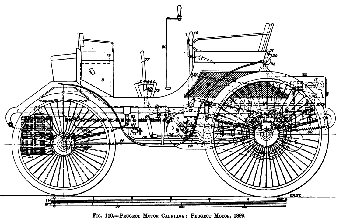
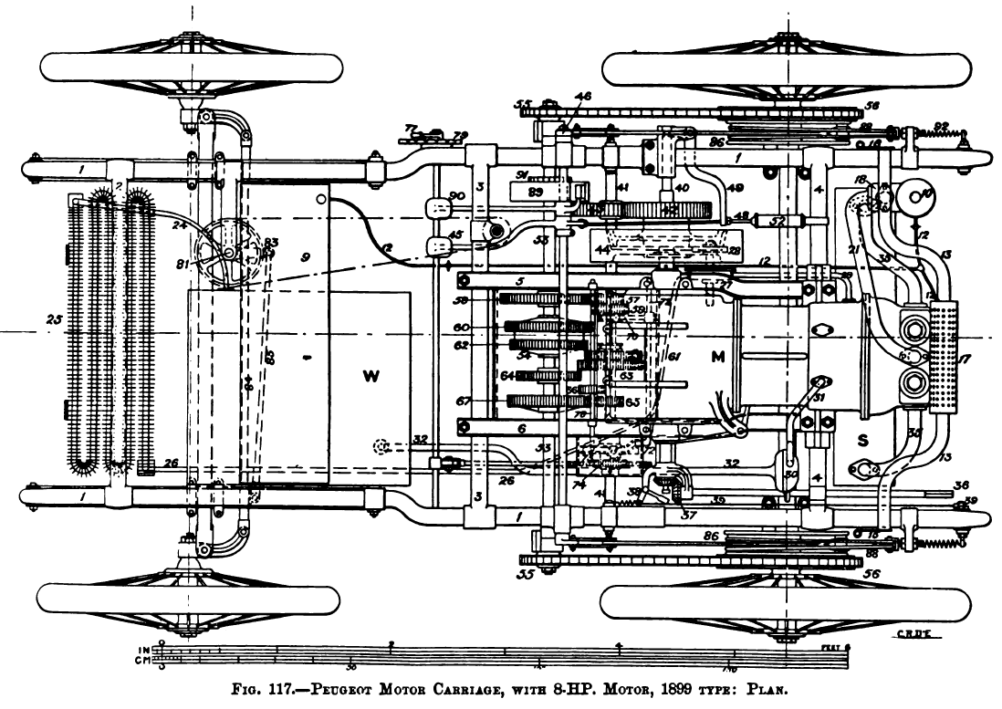
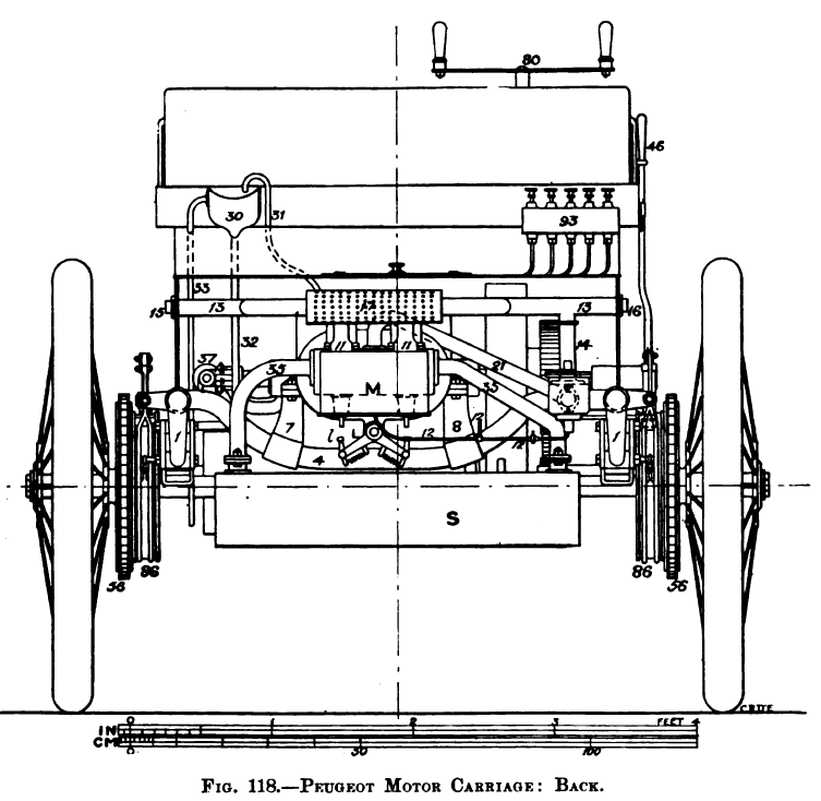
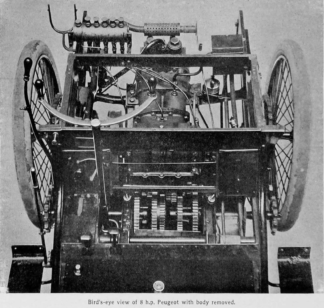
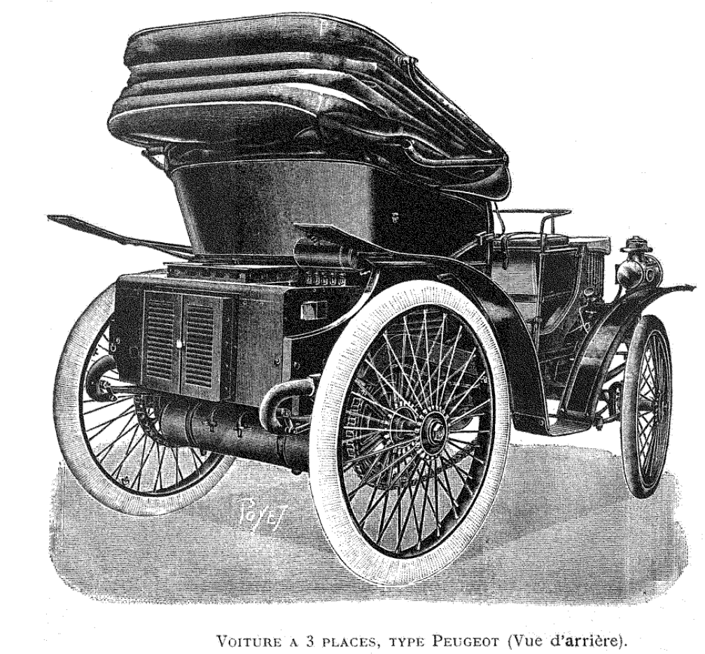
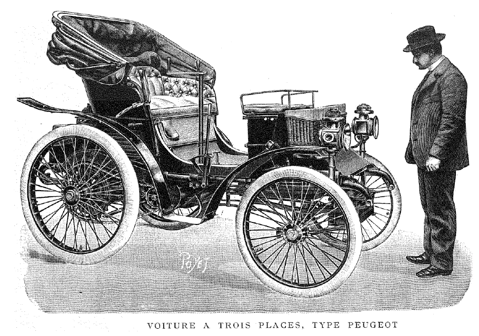
Figs. 116-123 show a side elevation, plan, and back view of a Peugeot carriage, with 8-HP. motor, to seat three persons. The motor, which is of the horizontal double-cylinder type, is enclosed by the body at the back of the principal seats. It drives through a friction clutch and spur gear on to a countershaft which extends across the carriage below the underframe. This countershaft in turn drives a similar one, by means of one of five sets of spur wheels and pinions, which give four forward speeds and one reverse speed to the vehicle. The power is finally transmitted from the second countershaft to the rear road wheels by means of pitch chain gears.
The steering of the vehicle is on the Ackerman principle, and is controlled by means of a conveniently-shaped hand bar in front of the driver's seat, a double pitch chain and sprocket wheels are employed to transmit the movement from the standard operated by the hand-steering bar to a second standard which carries the lever arm operating the steering wheels, so that the shocks and vibration are not transmitted to the steering bar.
There are three hand brakes controlling the forward movement of the vehicle. Two of these act direct on the road wheels, while the other, which is employed for all ordinary occasions, is placed on the countershaft, from which the rear wheels are driven. It is so arranged that the friction clutch is always disengaged before the brakes can be applied.
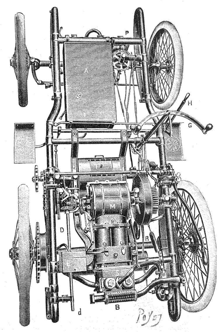
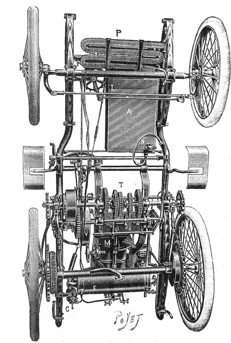
The oil and water tanks are carried below the small front seat, so that their weight is carried principally by the steering wheels. They are each of about 12 gallons capacity, so that very long continuous runs may be undertaken. A radiator for cooling the circulating water is suspended in front below the frame. This is constructed chiefly of steel tubes, and consists of the side tubes 1, 1, Figs. 116, 117 and 118, to which are brazed the cross tubes 2, 3, 4. There are also two longitudinal channel bars 5, 6, which carry the motor and gear case. They are bolted to projecting lugs on the cross tube 3 in front, and to the brackets 7, 8, which are brazed on the bent tube 4 at the back. The underframe and body are carried from the axles by means of long single-leaf springs.
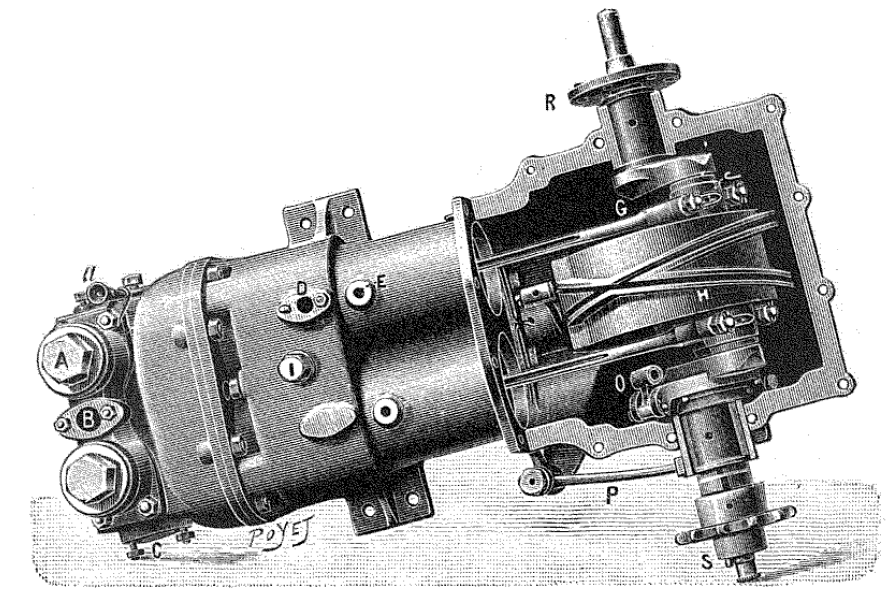
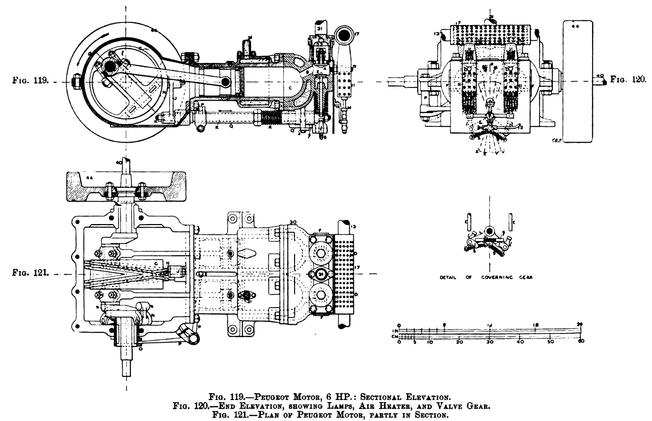
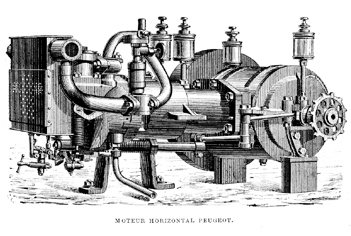
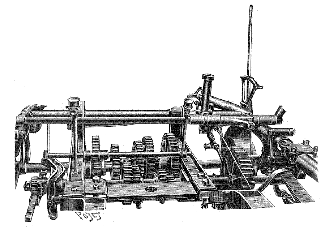
The motor м, which is shown in detail in Figs. 119-122, is of the Peugeot horizontal double-cylinder type, and develops 6-HP. at about 680 revolutions per minute. The cylinders are each 96 mm. = 3,75 in bore by 132 mm. = 5,168 in. stroke, both pistons acting on one crank, so that there is one working stroke for every revolution.
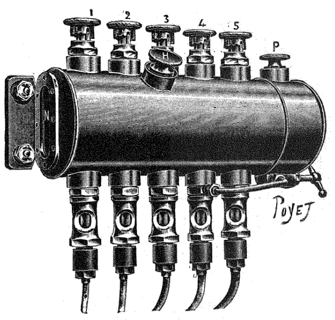
The petrol supply is carried in the tank 9, Figs. 116 and 117, below the front seat. This tank feeds the float vessel 10, Fig. 117, of the carburetor, and the ignition tube burners 11, 11, Figs. 119 and 120, through the pipe 12. The float vessel and carburetor, Fig. 122, which are of the Daimler-Maybach type, are carried from the air supply pipe 13 by means of the connection 14, Fig. 114. The supply of air to pipe 13 is regulated by the slides 15, 16, by means of which the ends of the pipe may be opened or closed to any desired extent. The air sucked in at 15 is heated in the portion of the tube 13, where it is surrounded by the cage 17, placed directly above the burners 11, 11; and passes down the pipe 14 into the mixing chamber 18 of the carburetor, the quantity admitted being regulated by the slide 19, Figs. 116 and 122, which is controlled from the driver's seat by means of the milled hand wheel 20, Fig. 116. On each suction stroke of the motor the charge is drawn from the chamber 18, and through the pipe 21 into the admission chamber 22 of the motor.
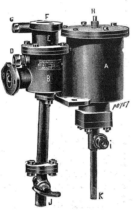
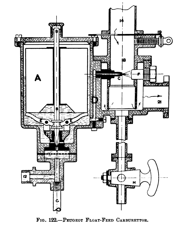
The float-feed carburetor is seen in detain Fig. 122. The action of the float a is the same as in the Daimler-Maybach float-feed spray-making carburetors already described, but the pivoted arms e, which engage with the collars on the needle valve b, are below, instead of on the top, of the float, the weight of the needle valve being sufficient to tend always to make it sit upon its seat against the lifting tendency of the levers. When the supply of petrol falls, the float a sits upon the outer ends of the arms E, and these lift the valve b, and permit the inflow of petrol through the pipe 12. On the outstroke of the motor piston, air is drawn in through pipe 14, past the slide 19, on its way to the cylinder through pipe 21. At c it passes the petrol spraying jet which is fed through the passage d, and by induction draws therefrom a spray which is broken upon the end of the plug f, and carried with the air which is carbureted by its vaporization. At g is a for emptying the carburetor float vessel, and at is a cock for emptying the carburetor.
The action of the valves is identical with that of the Daimler motor. On the suction stroke the admission valve a, Fig. 119, opens against the resistance of the spring above it, and allows the to pass from the chamber 22 by way of port в into the cylinder. On the return stroke it is compressed into the combustion chamber c and port space b, and fired by the ignition tube d. After the working stroke is completed, the exhaust valve e is lifted, and the products of combustion escape by way of port forwarding and pipe 35, Figs. 117 and 118, into the silencer s.
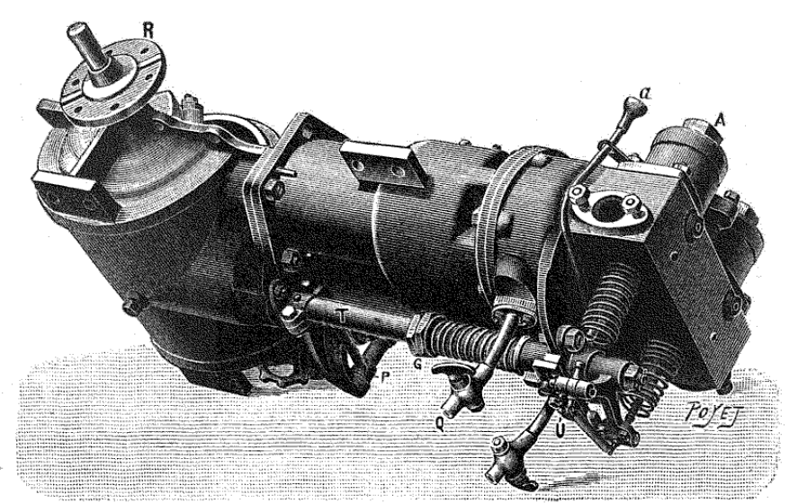
The exhaust valves are operated by means of the cam a, Figs. 119 and 121, which is mounted on the center of the crank shaft between the connecting rod heads. The cam consists of a drum, on the surface of which is a groove, as seen in Fig. 121, in which runs the tongue h, pivoted at the end of the arm j, which is mounted on the longitudinal solid shaft k, Fig. 119.
At the back end of this shaft is a bell crank lever l, at the ends of the arms of which are pivoted the pushers L L, held in position by springs S S.
As the crank shaft revolves, the pivoted tongue a, sliding in the groove of the cam G, causes the arm , which stands vertically when is at the crossing point of the groove, to rock to a maximum distance to one side and back to the vertical for one revolution of the cam, and then to repeat the same motion on the other side of the vertical position for the next revolution, and so on. It will be seen that the two grooves in the periphery of the big cam across each other just above the point occupied by the tongue, as shown in Fig. 121, and that the tongue being of some length the grooves act as rails and facing points, so that the tongue is directed at the crossing so as to follow the continuation of the greove it occupied before reaching the crossing. The change over from one to the other is determined by the change in angular position, which it gets in running in the part of the groove remote from the crossing. The movement of the arm is imparted to the longitudinal shaft k, and causes the arms of the bell crank lever to rise and fall alternately, so that the pushers ll strike the ends of the spindles of the exhaust valves see, and each valve is held open alternately for half a revolution once every revolution of the engine shaft.
The governor n is mounted on the crank shaft at one side of the crank case, Fig. 121. When the normal speed is exceeded, the balls n n fly apart, and pull the sliding brush o inwards. This operates the bell crank p, causing the sleeve q, Fig. 119, which slides on the shaft k, to be pushed in the direction of the arrow, Fig. 119, against the resistance of the spring r.
At the back end of the sleeve q is an arm Q' sliding on a guide 8. The arm q' has projections qq at its end, one on each side, so that looked at in plan it is shaped like the letter T. The movement of the sleeve q, above described, causes the pieces gq to be projected into the angular path of the projections tt, at the ends of the spindles which carry the pushers ll, so that these are caused to tilt inwards and to miss the ends of the exhaust valve spindles, so that the valves are not lifted until the speed of the engine is again reduced to the normal. The action of the governor on the exhaust valve spindle-pushers l l will be more clearly seen from the detail of governing gear shown below Fig. 116, in which the governor has pushed the sleeve of Fig. 115 away from the crank shaft by means of the bell crank lever p, so that one end q of the piece q' has come into contact with the tongue t of the pusher l, which but for the interposition of q would have been position for pushing the exhaust valve stem.
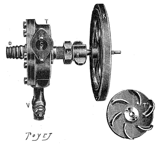
The cooling water for the cylinder jackets is carried in the tank w, Figs. 112 and 113, below the petrol tank q. The water flows from the tank by way of pipe 24, round the cooler 25, and thence by pipe 26 to the rotary pump 27, which is driven from the engine fly wheel by the friction wheel 28. The pump forces the water up into the cylinder jackets through the pipe 29, entering at 30, Fig. 121. After circulating round the jacket it is delivered through pipe 31 into the vessel 30. From this it flows down the pipe 32, back into the tank w. Should the flow of water into the vessel 30 be too rapid for pipe 32 to carry it off, it overflows through pipe 33, Fig. 118.
The exhaust gases from the engine pass through the pipes 35, into the silencer s, and thence escape into the atmosphere at the back of the vehicle from a large number of small holes at the bottom.
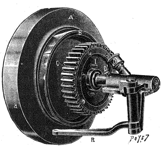
The motor is started by turning a key handle on the shaft 36, Fig.113, at the inner end of which is a bevel wheel 37, gearing with a similar wheel which is permissively keyed to the engine shaft by pulling the wire 39, by means of which the bell crank 38 presses the spring-resisted key inwards on the end of the crank shaft, and thus fixes the bevel wheel, which ordinarily runs loose on the shaft; the action of this loose wheel is similar to that already described with reference to Figs. 101 and 113. The extension 40 of the crank shaft, Figs. 117 and 121, drives the countershaft 41 by means of the spur wheels 42, 43, and is put into or out of gear with the engine by means of the cone friction clutch 44, which is the same as that already described with reference to Figs. 80 and 83.
The clutch is controlled both by the pedal 45 and by the brake lever 46. When the engine is put out of gear for the purpose of operating the speed changing device, the pedal 45 is depressed, pulling the wire 48 and lever 49. This causes the finger at the outer end of lever 49, which works in a groove turned in shaft 40, to move outwards, and thus pulls the clutch cone out of gear. On removing the foot from pedal 45, the spring 52 pulls the lever 49 back, and the finger pushes the clutch cone again into gear, in the position shown in plan in Fig. 117. By means of one or other of five sets of spur wheels and pinions, the countershaft 41 drives a parallel shaft 53, which carries the differential gear 54, and at either end the sprocket pinions 55 of the chain driving gear. The chain wheels 56 are attached to, and drive through the hubs of the rear road wheels.
The change gear wheels 57, 58, 59, 60, 61, 62, 63, 64, give four changes of speed for the forward direction of motion of the carriage; and the wheels 65, 66, 67 give one reverse speed. The wheels 57, 59, 61, 63 are mounted in pairs, each sliding independently on a feather on the countershaft 41. At one side of each of the two pairs is a grooved box, in which engage the forked ends of striking rods 70, 71. Rod 71 is not clearly shown in Fig. 117, as it is directly below the shaft 41. Rod 70 is fixed on the bar 72, which is free to slide in bearings at either end. One end of the bar is bent at right angles, the end being flattened, and engages in the groove of a cam disc 73, the groove of which is zig-zag in one fourth of the circumference, the rest being normal to shaft 41, on which the cam is free to turn. On the box of the cam disc is a pinion 74, with which gears a rack cut on the end of rod 76, Fig. 116, which can be moved backwards or forwards by means of the hand lever 77.
The rod 71, which controls the pair of wheels 61, 63, is fixed on bar 72a, similar to 72, and the reversing pinion 66 is carried on a movable bar 78, the end of which engages in the groove of the cam disc similarly to that of 72 and 72a.
When the hand lever 77 is at the position marked 2 on the sector 79, Figs. 116 and 117, the ends of all three bars 72, 72a, 73 are in the normal part of the cam groove, and all the wheels are out of gear. At portion 3, as shown, the cam has been rotated, and the end of bar 72 carried along the groove to the innermost point of the zig-zag, thus pushing the bar 72 a sufficient distance to put the wheels 57, 58 into gear as shown in Fig. 117, which gives the slowest speed to the carriage. During this operation the ends of the bars 72a, 78 have remained in the normal part of the groove, and consequently the wheels which they control have not been moved.
A further movement of the hand lever 77 to the position 4 causes the end of the bar 72 to be carried first into the normal position, thus putting 57, 58 out of gear, and then into the outermost part of the zig-zag, which puts 59 into gear with 60, corresponding to the second speed of the carriage.
During these movements the ends of bars 72a, 78 have still remained in the normal part of the groove. On moving lever 77 to position 5 the end of bar 72 runs into the normal part of the groove, putting 59, 60 out of gear, and continues there during any further movement of the lever 77 towards the driver. Just as the end of bar 72 is carried into the normal portion of the groove, that of 72a is moved into the zig-zag, and 61 gears with 62, giving the third speed. The final position, 6, of lever 77 puts these out of gear and causes 63 to gear with 64, giving the 4th and highest speed to the vehicle.
To reverse the direction of motion the hand lever 77 is first moved forward to position 2, when all the wheels will be out of gear, and then to portion 1, which continues the forward rotation of the cam disc and causes the end of bar 78 to travel outwards along the zig-zag, putting 66 into gear with 65, 67, the intervention of wheel 66 causing the reversal of direction of rotation.
The steering of the carriage is controlled by the curved hand bar at the top of the steering pillar 80, the motion being imparted to the short vertical spindle 81, Fig. 117, by means of the double set of sprocket wheels and pitch chains 82. The bent lever 83 on the lower side of this spindle is connected by rod 85 to the bar 84, and the motion imparted to the front wheels which run on stud axles pivoted at the ends of the fixed axle.
There are three brakes; two are band brakes 86, which act on drums bolted to the arms of the chain driving wheels. They are controlled by the lever 46, the movement of which also puts the friction clutch out of gear. The bands of the brakes 86 on the driving wheels are of leather, faced with wooden blocks, and are attached to the wire ropes 88, Figs. 116 and 117.
When these brakes are not in use the bands are held off the drums by means of the springs 92. It will be seen that these brakes are of the Lemoine or Spanish windlass kind. There is also the band brake 89, Fig. 117, on the countershaft 53, which is operated by means of the pedal 90.
The backward movement of the vehicle is prevented by means of a pawl which may be put into gear with the ratchet 91 on the countershaft 53, this taking the place of the sprag used by other makers. The lubricating oil for most of the principal working parts is fed from the combination lubricators 93 at the back of the driver's seat.
The wheels of the carriage are constructed with direct steel spokes and steel rims, with Michelin pneumatic tires. Fig. 123 shows one of these carriages, but fitted with touring and hooded body for Sir David Salomons. The wheels are fitted with solid tires.
Clutch