
“For most of the particulars we give we are indebted to La France Automobile. As will be seen from the drawings, the new Peugeot motor is a two-cylinder horizontal oil ( pétrole ) engine with a power strike on every fourth movement of each piston. The cylinders are parallel, and form part of the forward portion of a cylindrical case constructed to enclose the motor shaft, and have attached to them a chamber which is used as the compression chamber, and in which the valves are formed and carried.
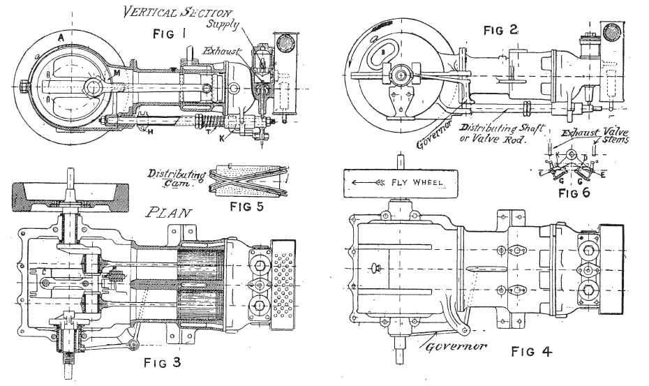
The motor-shaft bearings are fitted in the sides of the crank pit as shown in the sectional plan, fig. 3. The box is made in two halves, bolted together in the horizontal plane of the center of the motor shaft, which permits the contained mechanism to be entirely and easily removed by merely detaching the upper portion of the case. In the superior half, an opening, closed by a sliding cover A, is formed for inspectional and lubricating purposes. In the ends of the motor casing are two openings, fig. 2, which serve to cool the cylinders by the admission of air. The motor-axle is cranked after the manner of a ratched brace, as shown in fig. 3, and is actuated by the two connecting rods working directly thereon. On the axle within the box is fitted the valve rod cam (fig. 5), and also a centrifugal ball governor. This arrangement allows of the perfect and easy lubrication of the cylinders, connecting rod heads, the valve cam, and the governor, and protects all from dust and dirt. On the right side of the crank pit, where it issues from the same, the motor axle carries a disc fly-wheel arranged to take a friction cone, by which the power can be transmitted in any desired manner. On the left side the motor axle projects sufficiently to take a starting crank and handle. The valve chambers and the rear portion of the cylinders which are jacketed (fig. 3) are kept cool by water circulation. The explosive mixture is admitted to the cylinders by means of intake valves placed on the upper part of the case forming the compression chamber to each cylinder, the lower parts forming the exhaust valves.
To clean or repair the valves it is only necessary to unscrew the cap nuts seen on the upper part of each chamber, and then the feed and exhaust valves can be withdrawn without disturbing any other part of the mechanism of the motor. On the rear face of the compression and valve chamber are two ignition tubes, communicating respectively with the space between the two cylinder valves. Two pétrole burners keep these tubes at a proper temperature, and are enclosed in a lantern case arranged so as to heat the air employed in the composition of the explosive mixture. A slide M fixed to the extremity of a lever keyed to the distributing shaft is endowed with an angular movement by means of the channel on the cam with which it engages. This groove turning twice round a pulley keyed on the motor axle in one revolution thereof allows the exhaust valve to open once only to two revolutions of the motor. In this manner power is produced behind each piston on every fourth stroke, but the explosions being made successively, there is one to every revolution of the motor.
Each arm of the movement D (fig. 6) has jointed to one and a bent lever E, of which the projecting arm raises at the desired time the tappet of the opposing exhaust valve. The other arm of D is slightly in advance, nearly horizontal, and directed towards the center of the motor.
When the motor has any tendency to race, the ball governor, by the action of centrifugal force, overcomes the resistance of the spring T which encircles the prolongation of the socket or sleeve H on the valve rod or distributing shaft, and forces this sleeve backwards by means of an arrangement of curved levers. The sleeve H by means of a tube which surrounds the valve rod then comes into contact with the part K (fig. 1). This fitting is placed below the arms b (fig. 6) of the curved levers, and causes each of the little levers attached to the springs G to swing to the side valve tappet or stem, and the burnt products being retarded in their escape from the cylinder, delay in their turn the admission of the explosive mixture for the next charge. Then, as the motor slows down, the spring T causes the sleeve H to return, carrying the balls of the governor nearer the motor axle, and the small bent levers are again rendered able to properly open the exhaust ports.”
Как создание сайтов на WordPress отличается от работы на других CMS?