L’Automobile théorique et pratique, Baudry de Saunier, 1899
Worby Beaumont (Motor vehicles and motors, 1900):
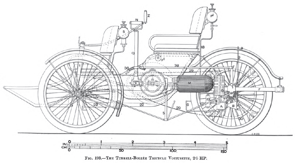
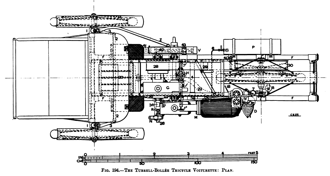
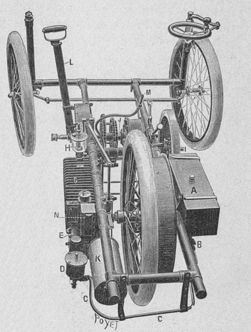
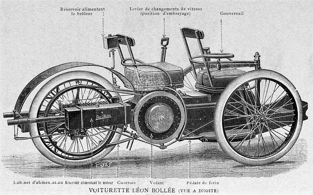
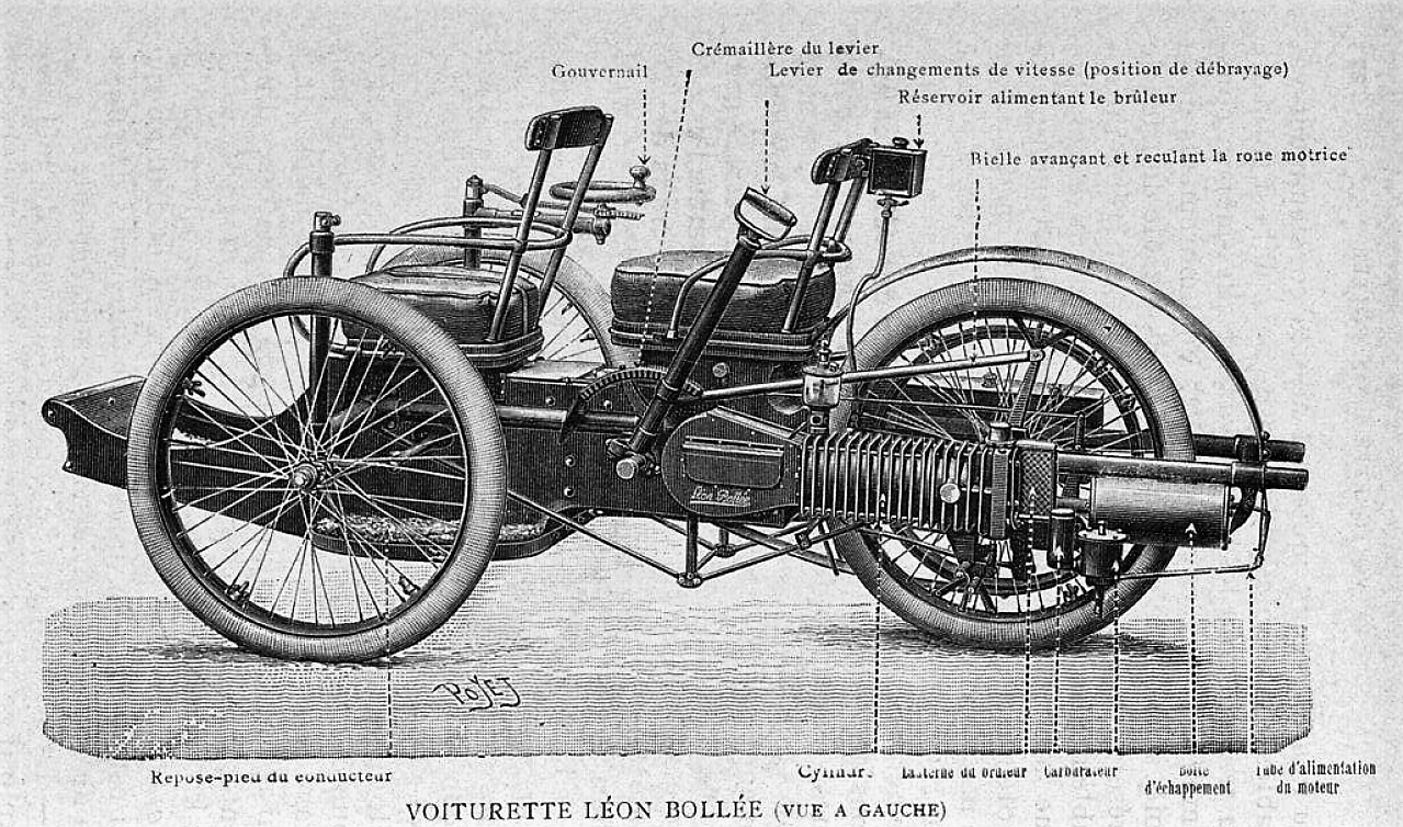
“Figs.193-201 show the form of Bollee tricycle as modified and made in England from the designs of Mr. C. McR. Turrell. The modifications do not affect the principles of the design, so that a description of this car will be in all essentials a description of the earlier Bollée car. The differences are chiefly in details of the motor, the arrangement and size of the seats, and in several small parts to which reference will be made. Figs. 193 and 194 show a side elevation and plan of this English-built three-wheeled voiturette.
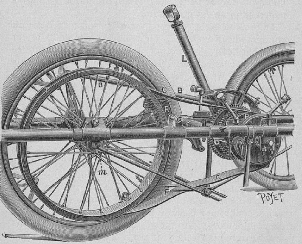
It is constructed to carry three persons, two in front and the driver behind, and weighs complete about 6 cwt. The motor is carried on the outside of the frame on the left-hand, the cooling of the cylinder and combustion chamber being effected by radiating ribs only, no water being carried. It drives, by means of one of three sets of spur wheels and pinions, a countershaft which in turn drives the rear road wheel by means of a belt, one of the chief features of Bollée’s invention being that the driving wheel axle is carried by levers pivoted on the frame of the car, so that by pushing the axle backwards or forwards the belt tension may be increased or decreased, and the motor mechanism thus put into or out of gear with the road driving wheel. The spur driving gear enables speeds of about 6, 12, and 18 miles per hour to be given to the car. There is no reverse motion, this being considered unnecessary for so light a vehicle, except in the eyes of the British law.
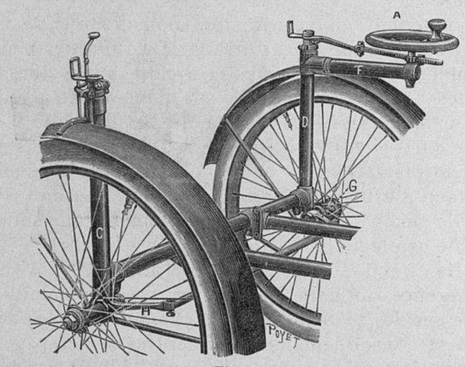
The underframe is constructed of steel tubes, and consists of a rectangular structure f, the front tube of which is prolonged on either side and carries at its ends the vertical tubes 1, which form heads for the vertical pivots of the steering wheel axles. To the top of the wheel pivot on the driver’s right hand is fixed the steering bar z, the wheel pivot on the opposite side being operated by means of the crosslink 2 connecting the arms 3. At about the center of the rectangular frame F is a cross stay tube 4, and the strut and trussing rods 5, one of which on each side give additional strength to the longitudinal tubes of the frame.
Motor
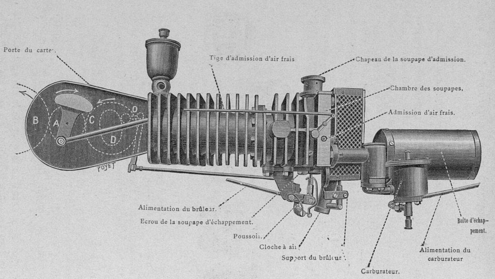
Baudry de Saunier, 1899
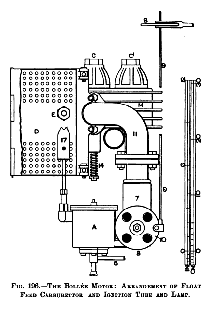
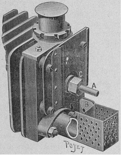
The motor M, seen in Figs. 193 and 194, and in detail in Figs. 195, 196, and 197, has a single horizontal cylinder without a water jacket, the cooling, as before mentioned, being effected by longitudinal radiating ribs which are about I in. thick and I in. deep, and cast with the cylinder and cylinder head. It develops 21, HP. at about 750 rev. per minute. For long continuous runs experience has shown that cooling by radiating ribs as used by Bollée is not effectual for a motor of this power, the portion of the head around the exhaust valve passage especially sometimes reaching red heat. When this happens, it is impossible to prevent the exhaust valve from leaking 8, which causes loss of power. More recent developments in this direction, as in the Darracq-Bollée car, have increased the efficiency of this cooling, but generally it may be said that water cooling is preferable for this size of motor.
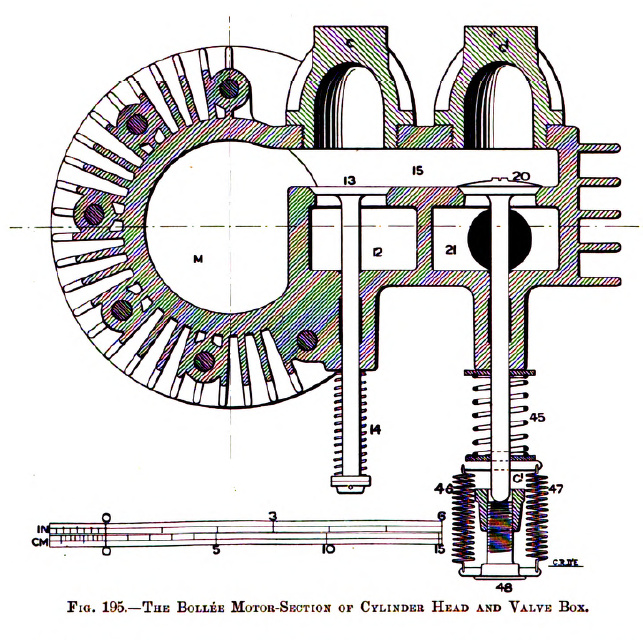
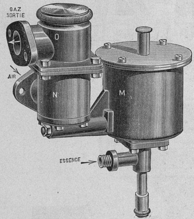
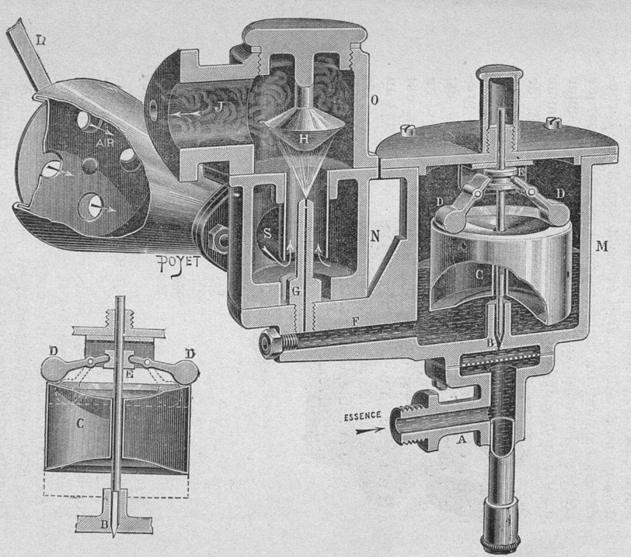
The supply of petrol for the motor is carried in the tank p, Fig. 194, on the right-hand side of the frame. It feeds the float vessel A of the carburetor, which is of the Phoenix-Daimler type, by means of the pipe 6, Figs. 193 and 194. As before described in connection with this form of carburetor, the float vessel a feeds the petrol as required into the carburetor 7, into which air is drawn through the conical pipe 8, Figs. 193 and 196, the openings in the end of which are seen in Fig. 196. By means of the small hand wheel в, at the upper end of the vertical rod 9, the plate 10, in which are holes corresponding to those in the mouth of the air tube, may be revolved for regulating the quantity of air admitted to the carburetor. On each suction stroke of the motor the admission valve 13 is lifted against the resistance of the spring 14, and the charge is drawn from the carburetor by way of pipe 11 to the chamber 12, and through the port 15 into the cylinder. On the next in-stroke it is compresses into the combustion chamber and port space 15, and fired by the ignition tube E, Fig. 196, at the back of the combustion chamber.
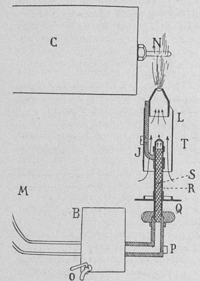
The tube is heated by a burner 17, both being enclosed in the box d. The oil supply for the burner is carried in the tank p’, at the back of the driver’s seat. It is fed by pipe 18 through the cleaning vessel 19, and thence to the burner, which is of similar construction to that used on the Panhard and Levassor car before described. On the completion of the working stroke of the piston, the exhaust valve 20, Fig. 195, is lifted, and the products of combustion pass into the chamber 21, and thence by pipe 22 to the silencer 23, which consists of four short tubes placed side by side horizontally. These tubes have their back ends connected by a chamber to which is also attached the exhaust pipe 22. The front ends of the tubes are closed by a plate, which is held by means of bolts connecting it with the flanges of the chamber. The gases escape from the silencer by means of holes formed in the bottom part of the tubes at their front ends.
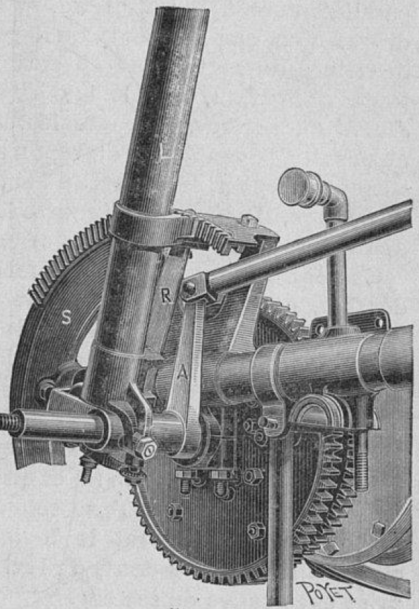
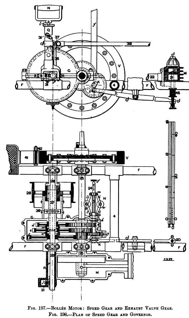
The exhaust valve 20 is operated by means of the cam K, Figs. 197, 198 and 201, at the outer end of the spindle 24, which is driven at a speed of one to two from the engine shaft 25 by means of the pinion a and wheel g. The cam K runs on a roller k at the end of the lever G1, the other end of which lifts the exhaust valve rod with which it is kept in contact by the spring arrangement seen in Figs. 195 and 197. The large spring 45 acts in the usual way in keeping the exhaust valve on its seat. The small springs 46 and 47, prevent the end of the lever G1, with its adjusting screw 48, from leaving elastic contact with the bottom of the exhaust valve stem. Rattle is thus prevented, and adjustment provided for. When the speed of the motor exceeds the normal, the governor H, Figs. 198 and 201, comes into action, and by displacing the cam K prevents the exhaust valve from being lifted.
The governor consists of the cylindrical weights w, connected by means of by way of links l to the joint-collar m, fixed on the spindle 24, and to corresponding joint projections n at the end of the tubular spindle h, which is driven by the gear wheel g. When the normal speed is exceeded, the governor acts in the usual way, and the spindle 24 is pulled in the direction of the arrow, Fig. 198, causing the cam k to miss the roller k at the end of the lever G1, and the exhaust valve is left closed until the speed is again reduced to the normal, and the cam brought back into place by means of the spring z on the spindle 24, when the exhaust valve is again lifted.
The motor is stopped by screwing in the milled head f1 at the left-hand side of the driver’s seat. This operates the horizontal spindle f, Fig. 201, the inner end of which is pressed against the upper end of the vertical bar g1, seen in section in plan, Fig. 198. The bar is pivoted from the seat frame, so that when r1 is turned the lower end of the bar g1 is pressed against the end of the spindle 24, and the cam K pushed out of contact with the roller k so that the exhaust valve cannot be lifted.
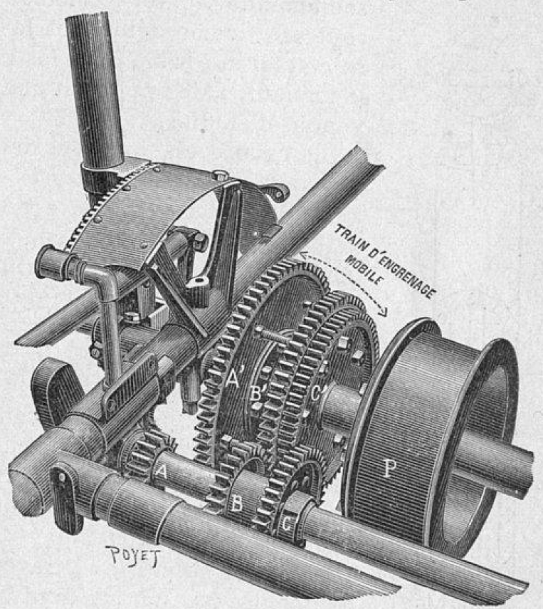
On the engine shaft 25 are keyed three spur pinions a, b, c, which gear with corresponding spur wheels d, e, f, carried on the countershaft 26 in such a manner that any one of them may be keyed to the sleeve 27 while the others run loose. The sleeve 27 carries at its opposite end the belt pulley 28, which drives the drum 30 by means of the open belt 29, the drum being attached to the driving wheel of the vehicle. Three changes of speed are obtained by means of the spur gear which is enclosed in the gear case G.
The speed changing is effected by means of the handle n, which also controls the mechanism for putting the motor into or out of gear with the road wheel, and for applying the principal brake.
These operations are effected by means of the parts now to be described.
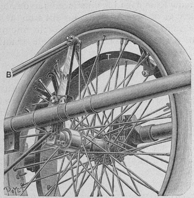
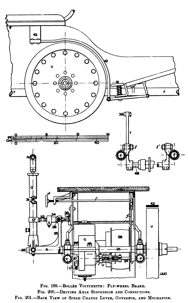
The handle n is mounted at the upper end of a vertical rod 31, Figs.197, 198 and 201, which passes through the hollow standard q, and carries at its lower end the pinion j, Fig. 198, which gears with a rack cut on the end of the countershaft 26. The handle and rod 31 may be fixed in one of three positions by means of the key l, Fig. 197. By lifting the handle against the resistance of the spring p at the lower end of the rod 31, it may be rotated, and the key l dropped into one of the three notches at the upper end of the standard Q, and held in place by the pressure of spring p. The lower end of the standard q is forked, as seen in Figs. 193 and 197, and pivoted transversely on the longitudinal pivots x, Fig. 197, at the end of the sleeve r, at one side of which is a groove r, in which the rack on shaft 26 is free to slide, so that the standard Q may be moved backwards or forwards, and with it the sleeve r. At the position of on the standard q is a projecting piece connected by links 32 to a short spindle 33 Fig. 201, which may be moved in the direction of its axis in the bearing 34 carried by the arm 35 from the sleeve r. At the inner end of the spindle 33 is a key which may be engaged with the toothed sector 36, Figs. 193, 194 and 201, which is attached to the frame, so that the standard q may be held at any required angular position on either side of the vertical. On the bearing 34 in which the spindle 33 slides, and at its inner end, is an ear 37, connected by the bar 38 to the upper end of the lever т, Figs. 193 and 200, which is pivoted att. Between the downwardly projecting arm of lever and a similar arm pivoted at t1 on the opposite side of the frame is carried the axle 49, on which the driving road wheel and belt drum 30 revolve, so that the distance between this axle and the countershaft 26 carrying the belt pulley 28 is controlled by the angular fore and aft movement of the standard q.
As above described, by turning the handle n the pinion j, gearing with the rack on the end of the countershaft 26, causes it to move transversely in its bearings. On the shaft 26, between the belt pulley 28 and the gear case g, is a collar 39, which is free to revolve in a closely-fitting box on the sleeve 27, so that the transverse movement of the shaft carries the sleeve with it. At one end of the sleeve 27 is a feather 8, which slides in a slot in the boss of the belt pulley 28, so that the pulley is always driven by the sleeve ; at the other end of the sleeve are four short feathers v, one in each quadrant, which fit into key ways in the bosses of the spur wheels d, e, f, spaces being left between the middle and the two outer wheel bosses, so that when the feathers v are in these spaces all three wheels are loose on the countershaft 26. The middle wheel e is carried between the outer wheels d, f by means of the collars w, w1 which are fixed to the wheels d, f, but which form bearings carrying the portions of the boss of wheel e, which project on either side of the wheel center. The three notches at the top of the standard in which the key l may be fixed correspond to the positions of the sleeve 27 at which one or other of the three wheels d, e, fare keyed to the sleeve.
In order to put the motor into or out of gear with the road wheel, the standard must first be pushed outwards away from the driver. This disengages the key on the end of the spindle 33 from the toothed sector 36, and so leaves the standard free. In order to put the motor into gear, or in other words, in order to tighten the belt 29, the standard q is then pushed forward, this movement being transmitted to the lever by means of the bar 38 as previously described, so that its upper arm moves in the same direction as the standard q, and consequently the axle 49 of the road wheel is pushed backwards, and thus the distance between the centers of the belt pulleys 28 and 30 increased and the belt 29 tightened. When the standard q is held in the vertical position the belt 29 is slack and the motor out of gear, and when the standard is moved backwards from this position the front portion of the surface of the belt drum 30 is pressed against a wooden block 40, Fig. 194. This is carried by the tubular frame, and when the pulley is pulled against it forms a powerful brake. There is also an auxiliary brake operated by depressing the foot-plate 41, Figs. 194 and 199, thus pressing the leather band 42 on the surface of the flywheel v, the upper end of the band being fixed to the framework at 43.
Some of the Bollée voiturettes have made long runs at high speeds, including the Paris-Dieppe race in 1897, when, was then the astonishing mean speed of 24:5 miles per hour over the whole distance was reached. Large numbers of these voiturettes have been made and used in France. They have not, however, been very favorably received in this country, although their power and handiness, and in some respects simplicity, are freely admitted.” (Worby Beaumont)
Drawings of Bolleee tricycle from the Baudry de Saunier book 1899: