
The Autocar, 1900:
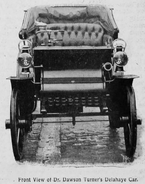
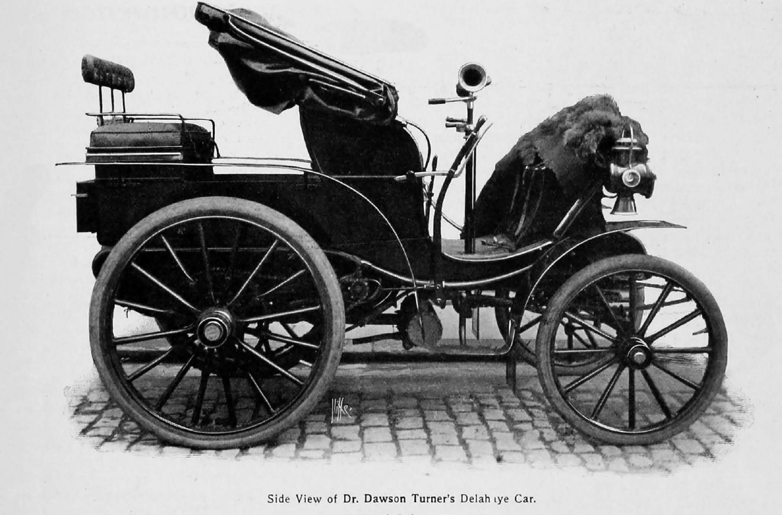
“The Delahaye car is one that is frequently discussed, but seldom seen in automobile circles in this country. The Right Hon. Cecil Duncombe is the owner of a nine horse-power Delahaye, which he has not vet driven to any great extent, and one has lately been seen about the metropolitan suburbs driven by Mr. Chas. Heyermanns, who, we believe, represents the Delahaye firm in this country. Dr. Dawson Turner, of Edinburgh, also possesses one of these cars, and, as our readers will recollect from Mr. C. Johnson’s interesting account of its performances between Kendal and Edinburgh in our last issue, the car is a fine, fast roadster. We reproduce some comprehensive and interesting drawings of the car and its motor and driving gear from La France Automobile, from which much of our description is translated.
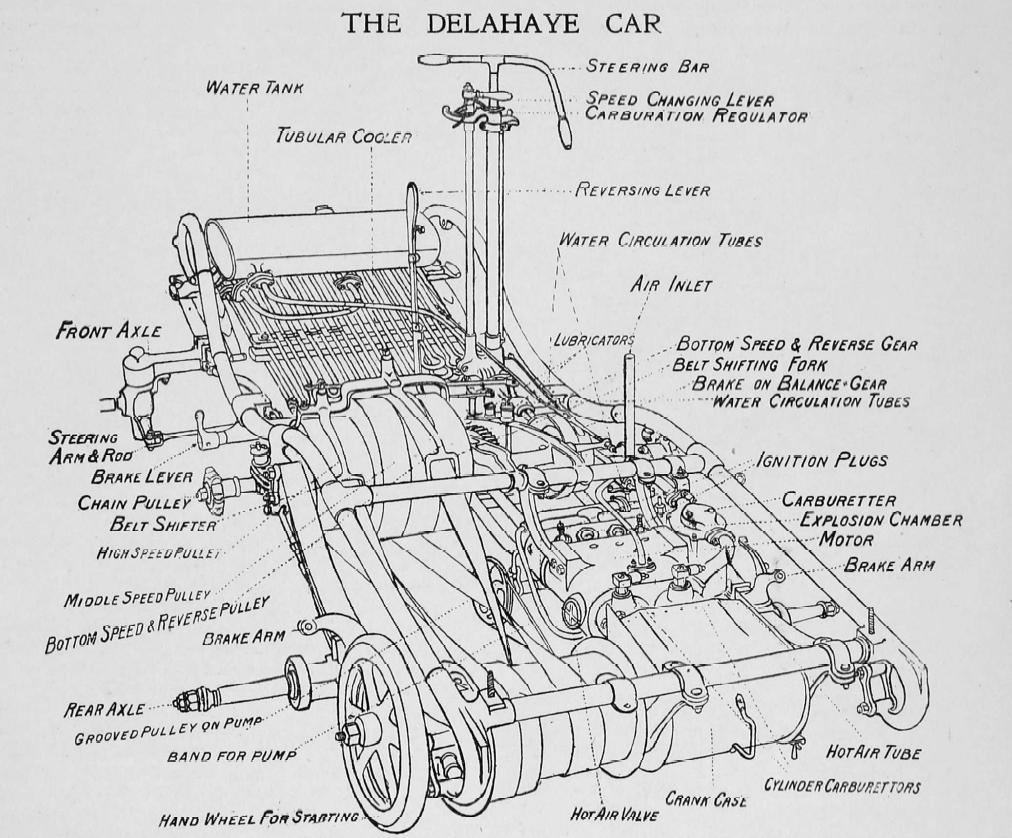
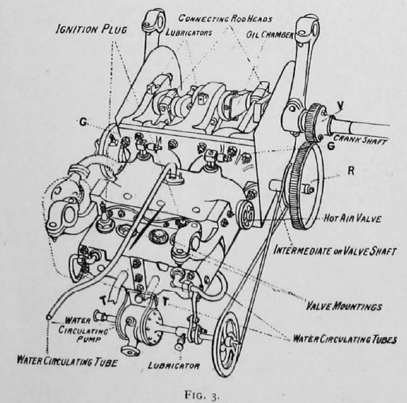
The principal characteristics of the Delahaye car are as follow : 1. Horizontal motor, no governor. 2. Electric ignition. 3. Belt transmission. Reference to fig. I enables us to grasp without difficulty the form of the underframe, which is of steel tube, springs, axles, and the disposition thereon and attachment thereto of the motor, pulleys, and belt gear, water tank, water cooler, coil, etc. The references on the drawing sufficiently name the parts. We will proceed now to discuss them in detail, leading off with the motor. The motor is a two-cylinder horizontal engine. The cranks are set at 1 80″, so that the engine gives an impulse once in every revolution of the crankshaft. The flywheel is set on the crankshaft at the left end thereof and outside the frame. On this shaft, immediately outside the crank chamber (see fig. 3), is fixed a pinion V gearing with the spur wheel R of twice its diameter. The valve shaft R accordingly revolves once to two revolutions of the pinion on the or motor shaft. The valves are four in number, and are placed in a line underneath the motor (see fig. 2). E E are the induction valves and S S the exhaust valves. To describe the action of the motor and these valves, the piston in one cylinder travels to the end thereof, the induction valve is thereby automatically raised (sucked), and the charge of explosive mixture allowed to fill the void within the cylinder. The piston returns, compressing the contents of the cylinder; the charge is fired by the electric spark, the piston is driven to the end of the cylinder, and, returning, expels the waste products of exploded gas. The exhaust opens at the crank moment when, or slightly before, the power stroke of the piston is concluded, and this is mechanically brought about in the following way: The spring seen encircling the valve stem projecting from the combustion chamber holds the valve hard down in its seating at all times, save when the striking lever P (fig. 2), which is actuated by a cam at the commencement of the exhausting stroke of the piston, raises the exhaust valve by pressure on the end of its stem, and so gives free vent to the burnt products in the cylinder.
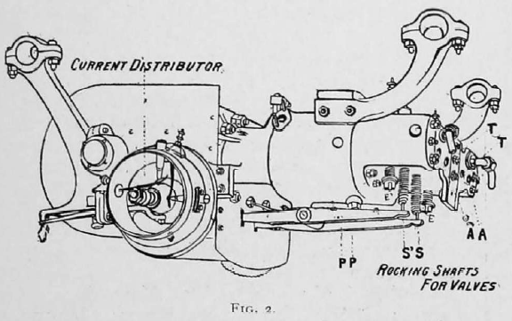
The cam is attached to the spindle upon which the spur wheel R (fig. 3) is carried, and thereby its proper relative movement to the travel of the piston is obtained. In the last quoted figure T T are the exhaust pipes communicating with the silencer.
The action of one induction valve and one exhaust valve only has been explained, but, of course, each pair are actuated, and behave similarly in relation to the cylinder to which they belong. The motor is arranged to run at from 900 to 950 revolutions per minute.
Lubrication of the motor. A Henry lubricator is fitted to the car, with five conduit tubes leading therefrom. Two of these pass to the cylinders, where to the admission of the lubricating oil is governed by two small valves similar to the induction valves at the points G G (fig. 3), and so constructed that the oil is not driven back into tubes on the compression stroke. The other three conduits from the lubricator lead the oil to the motor shaft bearings. The bearings on the crank-pins are lubricated from the shaft bearing. Centrifugal force is relied upon to cause the oil to flow from the bearing into the oil chambers, and thence through the passages drilled to the crank-pin bearings.
The supply of oil through the conduit leading to the central crankshaft bearing is, therefore, considerably larger than in the cases of the other two pipes.
The carburetor.
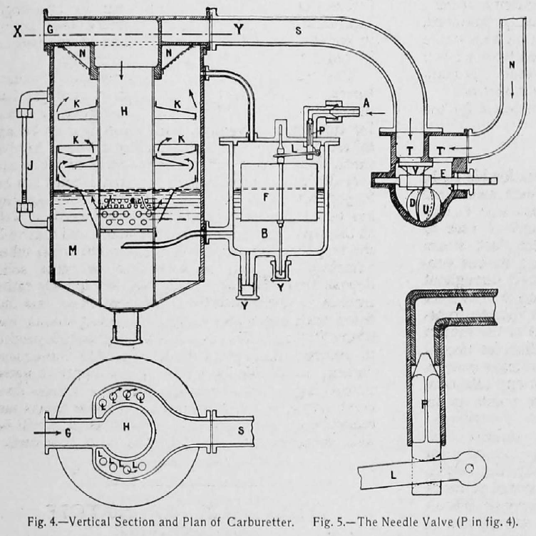
The vertical section and plan shown in fig. 4 enable us clearly to follow the method adopted to obtain thorough carburation of the air. The petrol flows from the petrol tank through the pipe A, falling into the float chamber B. The float F is so fitted that, floating in the petrol in the float chamber, it actuates the lever L, and closes the mouth of the pipe A by means of the needle P, when the petrol is at the required level in the carburetor M. The detail of this needle valve is clearly shown in fig. 5.
The action of the float is so obvious that it need not be further described. The level of the petrol is shown by the gauge glass J, fig. 4. Air heated by passing through a pipe, which on its way to the carburetor is caused to encircle the cylinders, arrives by the tube G, passes down tube H, and is drawn through the petrol by the small holes below the surface of the spirit into the chamber K, where the now petrol-vapor ladened air follows the course shown by the arrows between the copper wings, still taking up petrol vapor, with which, of course, the chamber K is charged to the inverted metal gauze cone N N, and on to the tube S by the holes L, shown in the plan.
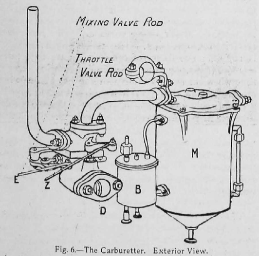
The tube S leads the carbureted hot air to the third member of the carburetor, where cold air arriving by the tube N dilutes the mixture. Below the two openings T T there runs a closing plate V controlled by means of the rod E, whereby the proportions of carbureted hot air and cold air are controlled. The opening D in the side of the lower semi-circular shaped part of the mixing chamber is the feed to the induction valves, and here is set a throttle valve U, the existence of which does away with any necessity for a governor. This valve gives the driver perfect control over the amount of mixture he allows to pass to the engine. When the car is at a standstill, sufficient mixture only is allowed to pass to keep the motor running. The mixing valve is regulated by a small angle lever placed above the steering, and the throttle valve is closed by means of a pedal worked by the left foot, and communicating with the rod Z, fig. 6. Under the float chamber B are two washout taps Y Y, fig. 4. In the central one the lower float rod is held. A similar wash-out opening is provided at the bottom of the carburetor itself.
The ignition.
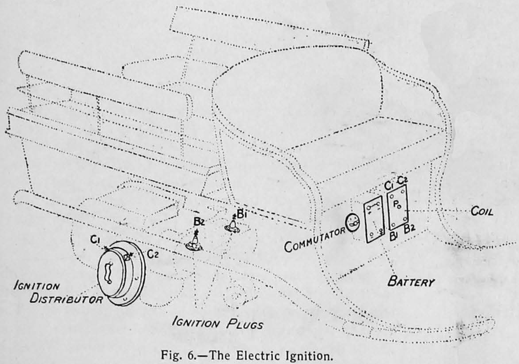
As we have already stated, the electric spark is employed to fire the compressed explosive charges in the cylinders. The apparatus necessary to effect this consists of accumulators, a coil, a current distributer, two sparking plugs, and a commutator.
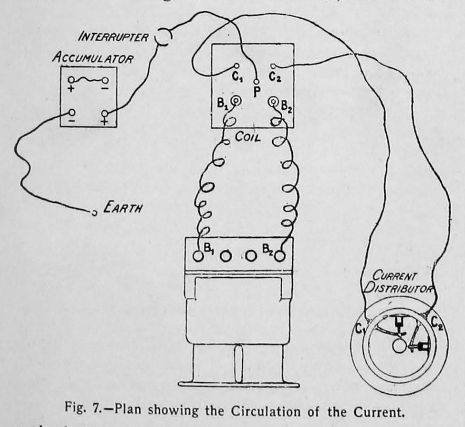
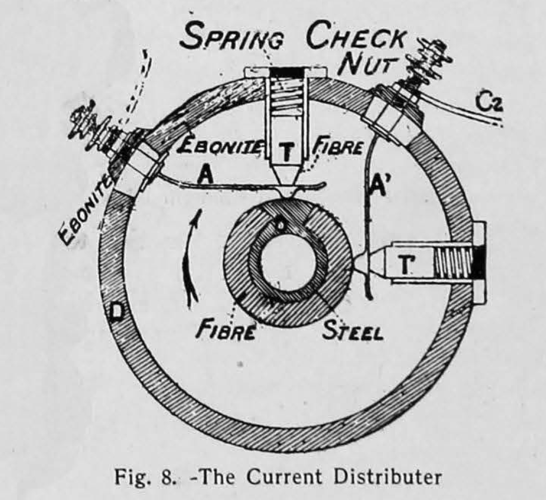
The accumulators and the coil are carried in a case in the forepart of the vehicle (fig. 6). Two wires pass from the accumulator, one earthing through the motor to a nut or bolt of which it is attached, and the other leads to the commutator, whence it is continued to the terminal P on the coil (fig. 7). This coil is made with four additional terminals B,, B,, C1, and C, (fig. 7), the two former being connected to the two sparking plugs on the motor B communicating with the left, and B, with the right cylinder. The terminals C, and C, are connected with the current distributor placed on the right side of the motor, and carried on the half-time shaft, which has been referred to as driven by pinion spur gearing, and running at half the speed of the motorshaft (fig. 3). The distributer is composed of a ring of ebonite D, to the interior of which are fixed two steel blades A A1, attached as to their outward ends to the wires C, and C, from the coil, and having their inner extremities carried on a steel collar surrounded by a fibre ring except between B C (fig. 8). The blades A A1 are kept in contact with the fibre-steel collar by the spring-backed studs T T1 the points of which are formed of fibre. The collar O revolves in the direction of the arrow.
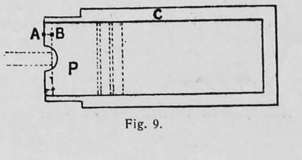
The spark. In order to obtain the best firing results it is necessary that the spark should be produced in the cylinder when the piston is in a certain position. This position is when the outer rim of the piston is 10 mm. from the open end of the cylinder, that is to say, when the distance from A to B (fig. 9) is 10 mm. for the eight horse-power motors and 8 mm for the nine and a half horse-power motors.
Water circulation.
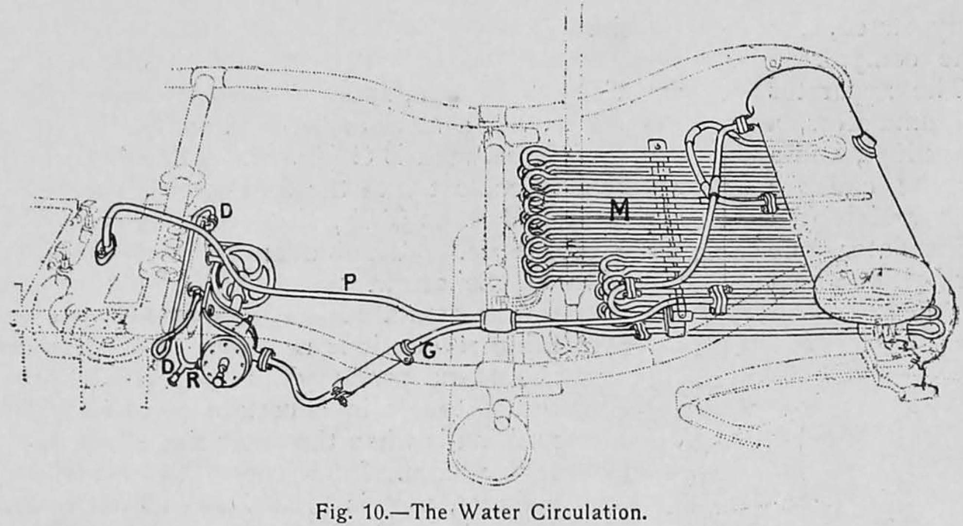
The centrifugal pump employed to circulate the cooling water through tank, coolers, and cylinder jackets is fixed either in front or above the motor. It is actuated by belt and pulleys from the half-time shaft, as shown in fig. 3. The water passes first to the water-jacket of the valve chambers by the pipe R (fig. 10), thence by the pipe D passes round the cylinder jackets and issues to the cooler M by the pipe P. This radiator is carried under the fore-carriage. It is composed of three stages of tubes so disposed that the current of air caused by the travel of the car passes equally between them. The heated water from the cylinder jackets circulates first in the two lower stages of tube, and then enters the tank above. It issues thence to travel by means of the upper layers of tube and the tube G back to the circulating pump.
A safety tube in the tank, serving also as a waste pipe, permits of the escape of any steam which might form.
Change of speeds.
This is obtained by shifting the belts from the loose to fast pulleys in the usual way. The combination of the pulleys and the toothed gearing gives three forward and one backward speeds (see fig. 11). The motorshaft carries a drum made with two diameters, the smaller for the low speed and the larger for the third speed.
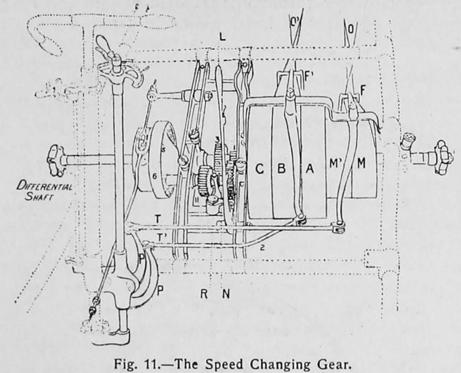
The countershaft (fig. 11) carries two groups of pulleys, the first, for the high speed M M1, being of equal diameter, the striker F moving the belt O from one to the other. The second group, by which the first, second, and reverse speeds are obtained, is composed of three pulleys A, B, C. The pulley B is loose, and when the belt O1 is running on B there is no transmission. When this belt is moved to the fast pulley A by the striker F1, the first speed is obtained. We obtain the second speed and the reverse by means of the gearing shown in figs. 12 and 13. The pulley C, in fact, drives this train of gearing. The toothed wheels 1, 2, and 3 are fast upon their respective shafts; 4 and 5 are mounted on a sleeve sliding on the shaft N. The movement of this sleeve carrying its two pinions is obtained through the fork R and the lever L (fig. 13).
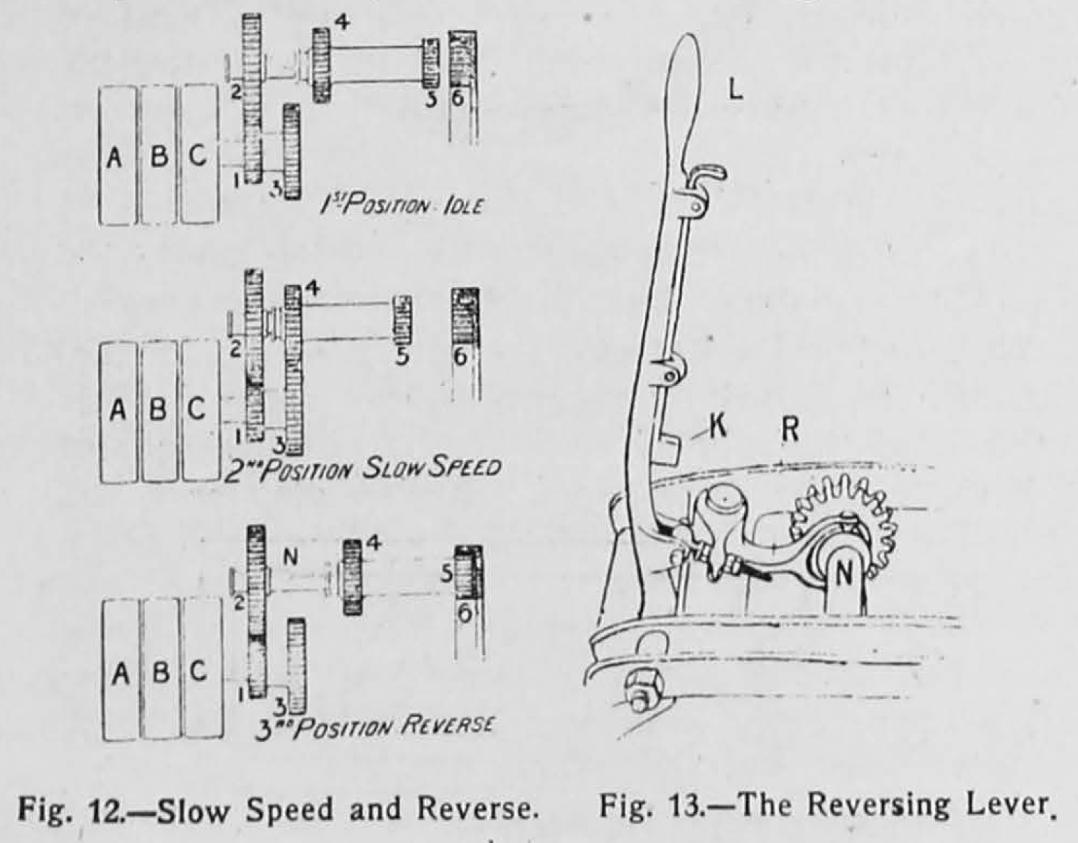
In the first position the gear is idle ; in the second position, 3 and 4 being in gear, we have the first speed ; in the third position S is into gear with 6, which is an internally-toothed wheel, and we have the backward speed. The forks F F1 are actuated by the rods TT’ (fig. 11), which by means of the arms P P1 are connected to two levers placed beneath. The necessary changes of gear for the first speed and the reverse are obtained by means of the locking lever L (fig. 13) and the striking of the belt O on to the pulley C. The pulleys surround the differential gear. At each end of the countershaft are the chain pinions. When it is desired to change from the second to the first speed the clutch is thrown out, and the belt O1 caused to pass on to the loose pulley B. The motor is slowed by pressing the pedal that closes the throttle valve, and the lever L is pushed forward. The motor is started by means of the small exterior fly-wheel V (fig. 1), and means are provided by which the compression is partially relieved during the operation.
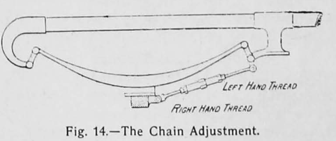
The method of tensioning or slacking off the chains is clearly shown in fig. 14, and needs no explanation. We may add, however, that it is a method which does not appeal to us very strongly, as the coupling rod is always in compression when is driving. The steering is simple, the steering standard, which is fitted with a wheel, having at its lower end a toothed wheel with six teeth, connected by a chain to a wheel of twenty-one teeth, which by means of a crank made with a long slot affords a traversing movement to the steering bar connecting the short arms of the wheel spindles.
The car has three brakes one band brake on the countershaft pedal applied in the usual way, and two band brakes on the hubs of the driving wheels lever applied.
“