
He was born at Bickington (Chipley), Newton Abbott and educated. In 1879 Butler went to work for Brown and May at the North Wilts Foundry. In 1881 he moved to London to work for the Hatcham Ironworks.
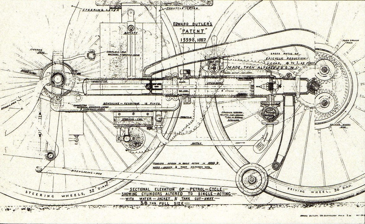
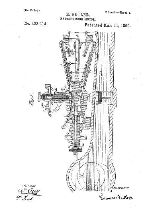
Edward Butler was the only Englishman who made a petrol-engine vehicle in the 1880s. In 1884 he exhibited a drawing of a tricycle in the Stanley Cycle Show. He took out the patent № 15598 on November 15th, “Improvement in Hydrocarbon Motors and in the Method of their Application for the Propulsion of Tricycles and other Light Vehicles”. The tricycle was completed at the Merryweather Fire Engine works at Greenwich in 1888.
Among its advanced features were Ackerman steering (the first use of the system in a petrol-engined car), a spray carburetor (five years before Maybach) and mechanically operated inlet valves.
As at first made, the engine was two-stroke with a capacity of 1041 cc coupled direct to the single driving wheel. This arrangement required a slow speed of rotation, which for several reasonwould not work well. The two pairs of valves and the magneto ignition arrangement were also unsatisfactory. Subsequently the pistons and valves were altered for single acting, and instead of direct driving. There was an epicyclic gear in the hub of the single driver, with a ratio of 1 in 6.
Worby Beaumont (“The Motor vehicles and motors”, 1900) wrote:
“A bichromate battery and sparking coil were substituted for the magneto machine. The cylinders were water cooled, the guard over the driving wheel being hollow and forming a water reservoir. The cylinders were at first 2 5 in. diameter and 8-in. stroke, the stroke being reduced to 5 in. when the higher speed of about 500 revolutions per minute was adopted with the gearing of 1 to 6. The vaporizer was of the spray-making type, as afterwards used by Butler in his little domestic gasoline motor. Solid rubber tires were used, 1,5 in diameter on the driver, and 1,25 in diameter on the steering wheels, which were on Ackerman axles, connected and actuated by a strong handle on both sides.
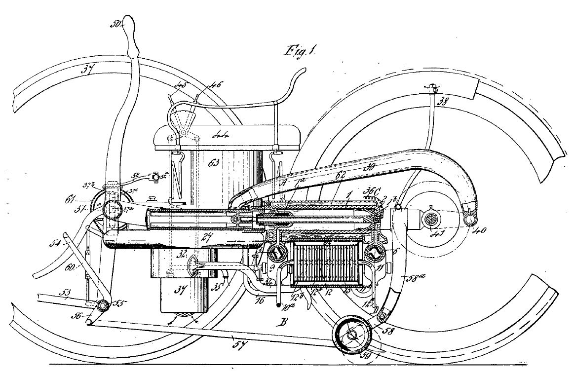
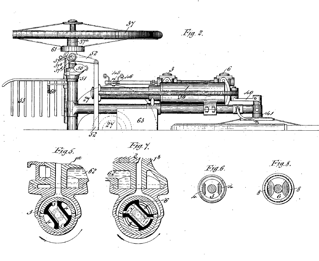
In the cylinder, was a piston, with tubular piston rod connected to a cross-head, which worked in a tubular guide with side slots, through which passed the crosshead pin, embraced by the forked end of the hollow connecting rod. The crank was fixed on a tube on the driving-wheel axle, and drove through speed reducing gear in the wheel hub. The pistons were double acting, the in stroke drawing in air at the front and afterwards compressing it, the mixture then passing to the back end of the cylinder, in which alone combustion took place. The ignition took place at about one-fifth on the outstroke. Rotary valves were employed, below the cylinder. The air, before being drawn into a form of spray-making carburetor, entered an air purifier at and heater. The heater was simply a chamber into which exhaust pro ducts were delivered by the pipe, and through which air pipes passed on their way to the vaporizer. Thence the vapor passed into a storage chamber , and from it to the air and vapor adjusting chamber, by way of pipe and the vessel, in which was a series of sheets of gauze to prevent back ignition. The heated air is drawn in by the front side of the piston through the pipe, and the air-valve chamber, and thence through the pipe into the receiver.
The cylinders were jacketed, and cooling water was carried in the tank w and the hollow wheel case, between which and the tank there was a connecting pipe.
As a means of easily starting the motor, or in streets by preventing its driving, the roller on an arm pivoted below the letter, could be depressed by the lever, thus lifting the wheel from the ground.
The brake was applied by a foot lever, which pulled down a vertical rod seen behind it. There is a great deal in this specification which is of mechanical interest, and showing much knowledge of the behavior of air and spirit vapor, and of light oils, under some conditions. There were, as might generally be expected, far too many parts, and the proposed rotary valves would in all probability have proved a failure for the motor ends of the cylinder. The necessity, assumed or real, for avoiding the Beau de Rochas or Otto cycle, also introduced complications.”
Later on Butler redesigned the engine as a four-stroke, with the stroke reduced from 8 to 5 inches (200 to 125 mm) and a capacity of 650 cc. At 600 RPM , the engine developed 5/8 HP and gave the speed of 8-12 mph (13-19km/h).
Butler gave the name of his tricycle the Petro-Cycle. There was the first time that the word “petrol” was used.
The vehicle featured in an article in the 14 February 1891 issue of Scientific American, where it was stated that one gallon of fuel in the form of petroleum or benzene could propel the vehicle for forty miles at a speed of 3-10 mph.
The compressed charges are alternately ignited by an induced current of electricity passing across terminals fixed in the cylinder covers, the current being generated by a single fluid battery under the seat. Stopping and starting is effected by raising and lowering the driving wheel from the ground by a foot lever, the weight of this portion of the machine being then thrown upon small caster wheels.
The speed of the motor is regulated by a throttle valve lever, shown at one side, and overheating is prevented by water circulating through a radiating tank over the driving wheel. The tank is of 31 gallons capacity, but with a very large proportionate surface. handles actuating the front wheels, which move on separate pivots, and the brake is applied to both of these wheels by a foot lever.
The weight of the machine is 280 pounds.
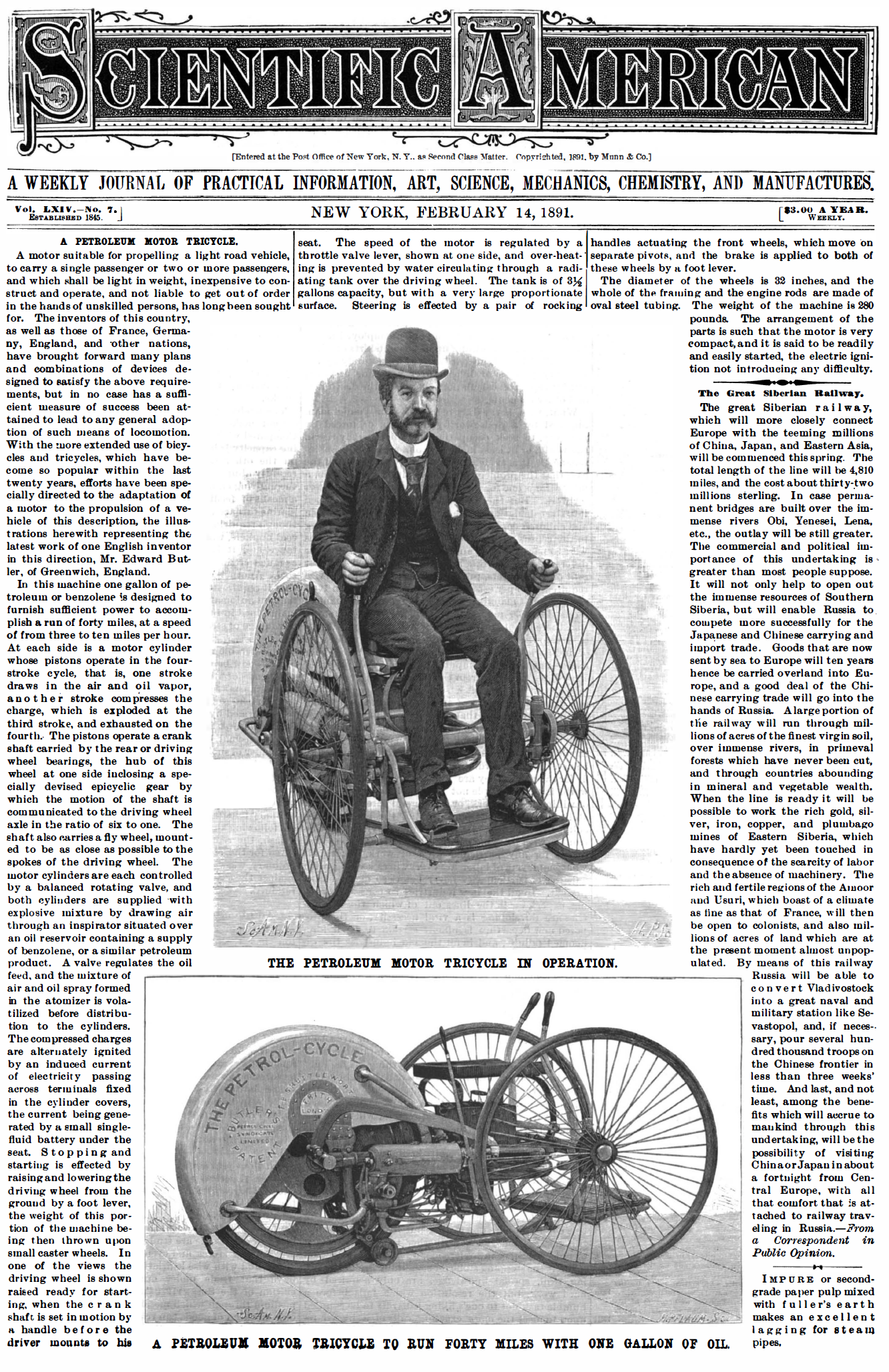
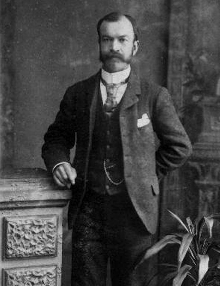
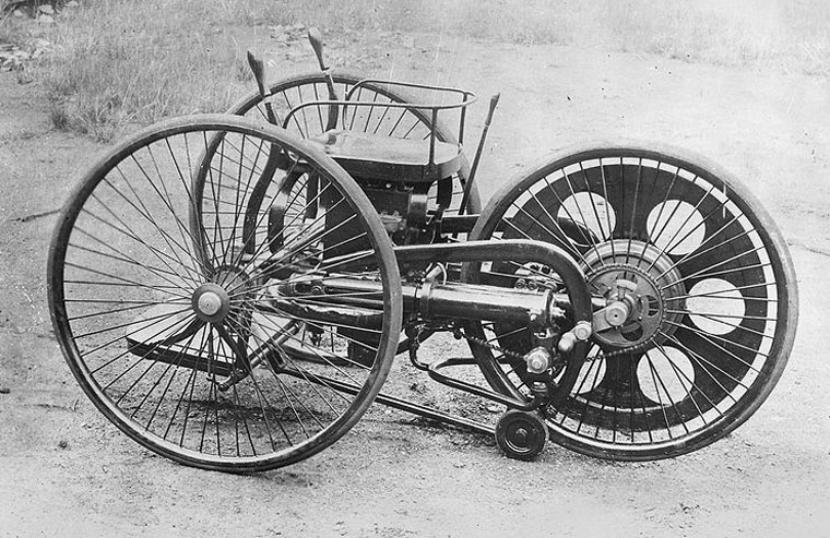
Edward Butler was photographed on his tricycle at Erith in May, 1889.·Six months later all further developments of this little motor carriage were abandoned because of the legal restriction in England.
In 1890 Butler wrote in the magazine The English Mechanic, “The authorities do not countenance its use on the roads, and I have abandoned in consequence any further development of it.”
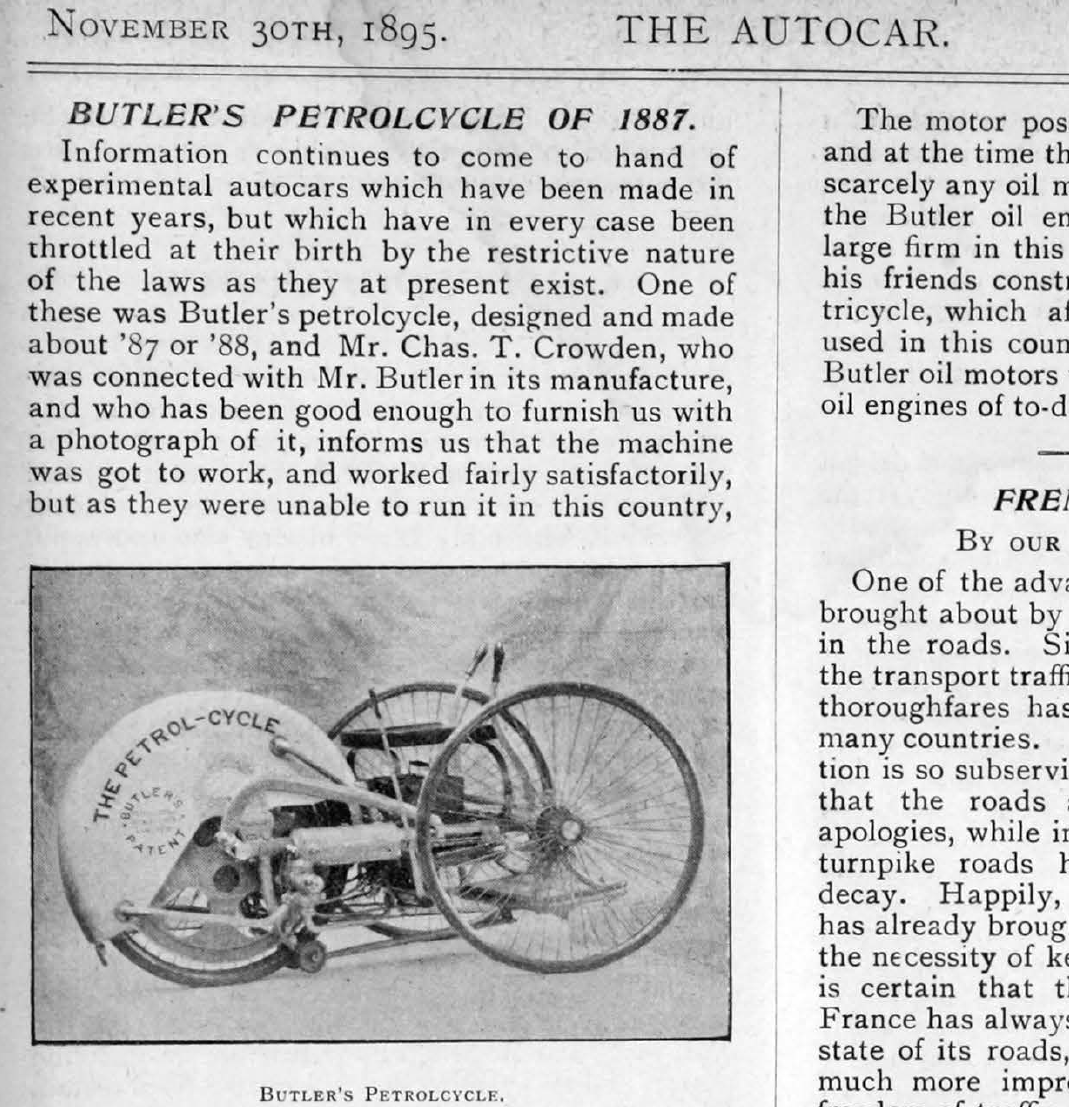
“Information continues to come to hand of experimental autocars which have been made in recent years, but which have in every case been throttled at their birth by the restrictive nature of the laws as they at present exist. One of these was Butler’s petrolcycle, designed and made about ’87 or ’88, and Mr. Chas. T. Crowden, who was connected with Mr. Butler in its manufacture, and who has been good enough to furnish us with a photograph of it, informs us that the machine was got to work, and worked fairly satisfactorily, but as they were unable to run it in this country, the syndicate who found the money for it to be built wou!d not go any further with it. Mr.Crowden gives the following particulars concerning it :
The machine has two steering wheels in front, and one driving wheel behind. On each side of the driving wheel are mounted two power cylinders, driving direct without intervention of gearing by means of two connecting rods and the cranks. Between the steering wheels is fixed a seat for the rider, and on each side are fitted two handles for the rider to steady himself at high speed, and at the same time manipulating the steering wheels. Each steering wheel is fitted with a powerful band brake actuated by a foot lever. Another foot lever was also provided for raising the driving wheel from the ground to start the motor running, and by taking the pressure of the foot slowly off the lever, the driving wheel was lowered to the ground or raised as required. The mudguard over the driving wheel was in the form of a water tank, and was used for supplying water to the jackets of the power cylinders. Petroleum was carried in a small vessel under the seat, from which it passed through a novel form of vaporizer, and thence to the cylinders, as required. To ignite the explosive mixture a small Wimshurst machine was tried, and this was soon abandoned for a Rhumkorf coil and battery. The direct driving was also given up, and a fly wheel was fitted on the driving wheel axle, driving the road wheel by means of an ingenious gearing, which allowed the motor to run at an increased number of revolutions.
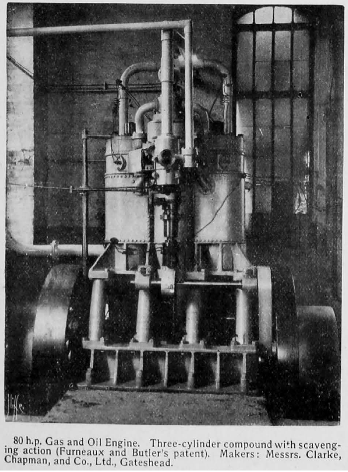
The motor possesses some very novel features, and at the time the machine was made there were scarcely any oil motors known. I might say that the Butler oil engine is now being made by a large firm in this country. Had Mr. Butler and his friends constructed an oil engine before the tricycle, which after it was made could not be used in this country, there is no doubt that the Butler oil motors would have been the best known oil engines of to-day.”
Due to general lack of interest, Butler broke up his machine for scrap in 1896, and sold the patent rights to Harry J. Lawson who continued manufacture of the engine for use in motorboats. Instead, Butler turned to making stationary and marine engines. His motor tricycle was in advance of its better-known contemporaries on several points.
1900 April 7th. Edward Butler wrote to “The Autocar” magazine mentioning the early attempts of Benz and Daimler and that he had drew up the plans for a vehicle in 1884, ‘Now that public attention is being drawn to the early attempts of the two German pioneers, Benz and Daimler, I trust that you may find space in your journal for an illustration of a small petrol vehicle, which I believe was absolutely the first made in this country, and if I could have interested any one to finance it when the drawings were exhibited at the Stanley Show in 1884, and the following year at the Inventions Exhibition, I should have been contemporaneous, if not earlier than either of them. Although I cannot claim to have done very much in the light of the present enormous development of the automotor trade, it may have been forgotten that I carried out a series of experiments in the perfecting of a motor vehicle at a time when progress was much hindered by the prejudice and want of interest – the motor part of which has been since used in many types of engines for industrial purposes”.
In 1901, the Court held (the case of the British Motor Traction Company), in which the famous Maybach patent for a float carburetor was invalidated. Butler’s patent played a significant role in this court decision, in which he described the same principles for his carburetor, which were described several years later in the Maybach patent.
The Automotor Journal (August 1901) wrote:
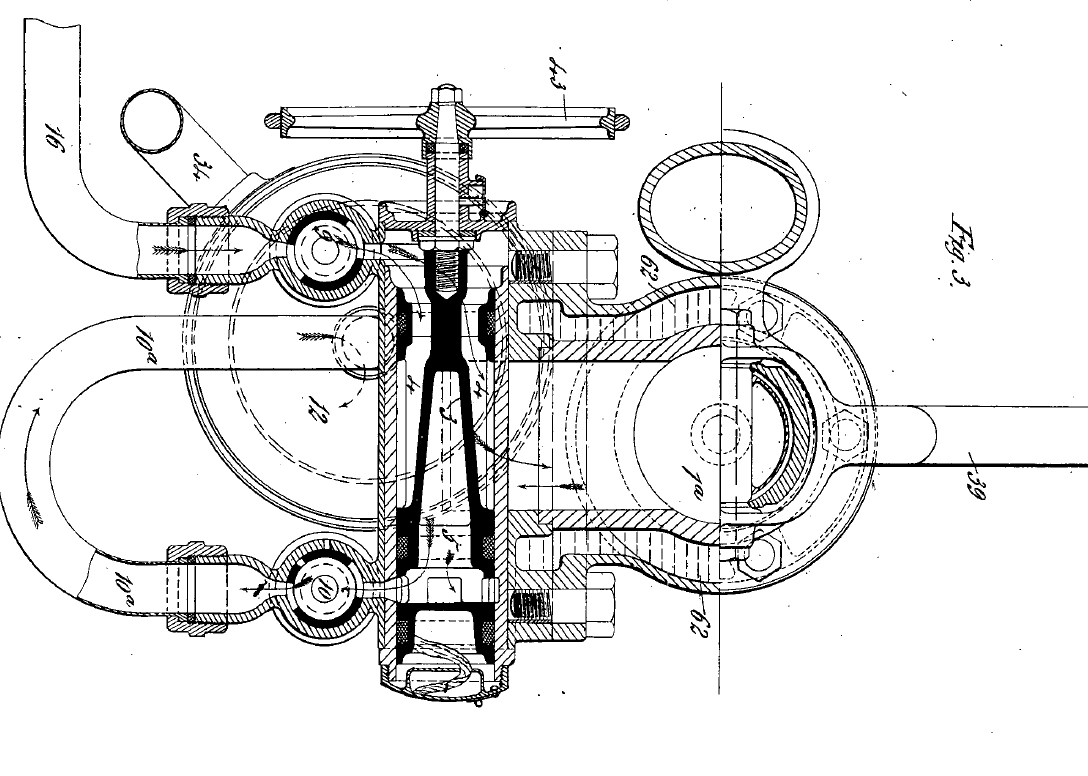
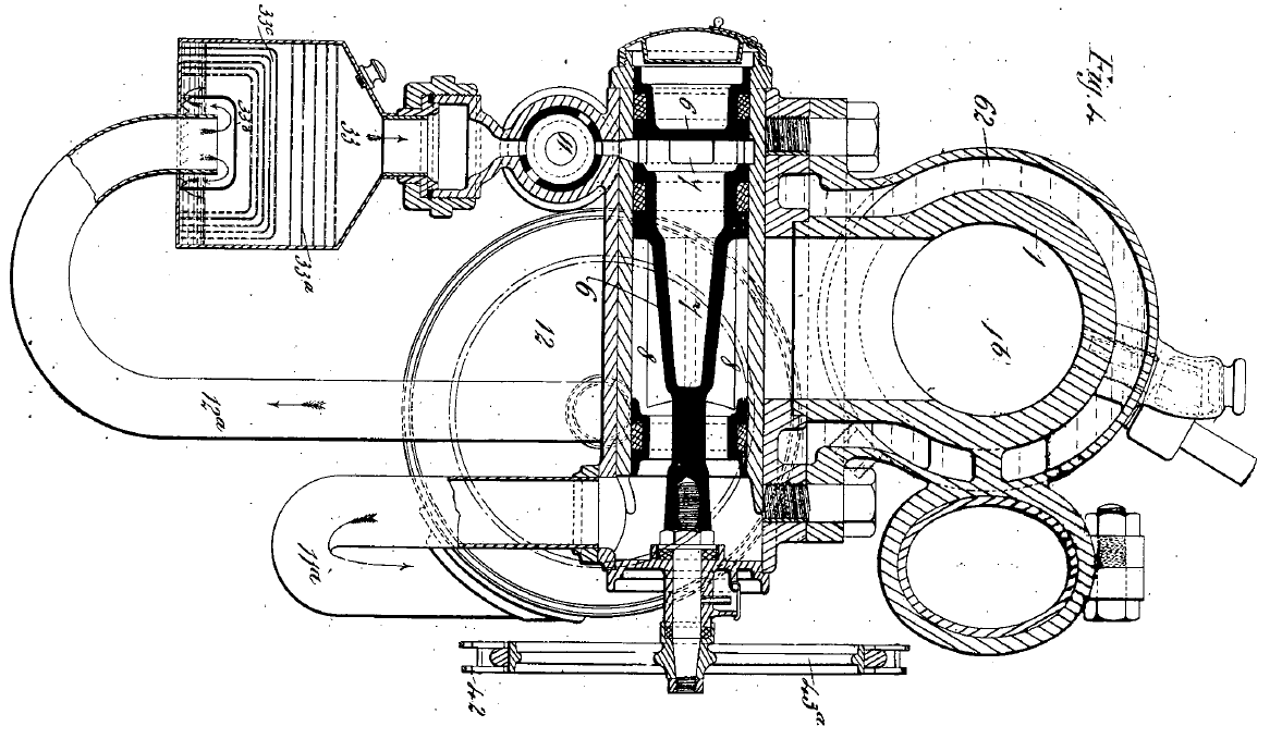
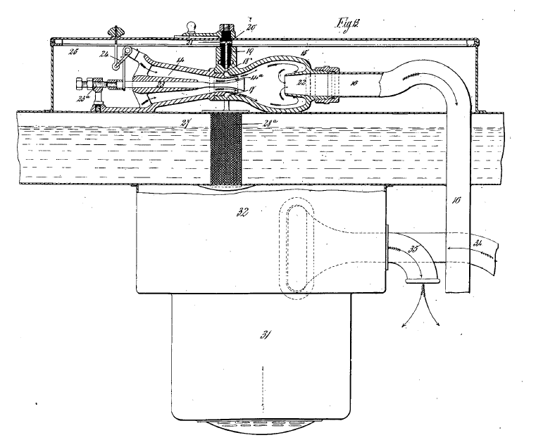
“The descriptions of Butler’s engine, which were mostly relied on in the trial, were his Specification No. 9,203, of 1899, more particularly Fig. 4, and an article in the Engineer, dated 25th July, 1890, pages 65 and 66, entitled Butler’s Domestic Petroleum Motor, and written by Mr. Worby Beaumont. The article in the Engineer, as far as it concerned the matter in hand, described an arrangement which, from the technical point of view at any rate, was substantially the same thing as Fig. 4, of Butler’s specification above referred to. In this arrangement we refer to Fig. 4 of Butler’s specification (the practical identity of the tube was allowed to pass in Court unchallenged) we have a cistern or small tank underneath the spraying appliance, in which the hydro-carbon oil is kept at a certain level by a valve controlled by a float (91). The intake passage leading towards the engine is conical, and in it is arranged a stepped cone (98) which chokes, and consequently increases the speed of the inrushing air, thereby tending to produce an improved atomizing effect. The small end of this cone is prolonged into a screw spindle which partially closes the main air inlet which is at the end of the conical tube (73). By adjusting a cylinder mounted on a screw (88), the air passing into the engine may be more or less throttled, according as the plug in question is screwed a longer or shorter distance into the cone. Of course the greater the throttling effect so produced, the greater is the suction. An annular passage (75) arranged in the casting where the two truncated cones come together receives the oil, which is led from the reservoir by a tube (77) to the upper part of the annulus, its admission being controlled by a set screw. The suction produced by the intake stroke of the piston causes both an inrush of air through the cone (73), and also causes the oil to rise through the tube (79), and to enter the annulus and to be sprayed out to the inwardly pointed edge of the annulus, where it comes in contact with the air rushing in behind it, is partially atomised thereby, and still further atomized by impinging upon the steps of the stepped cone. A non-return valve is arranged at the bottom of the tube (77) to prevent the oil running back when the engine stops, for the purpose of keeping the tube full of oil and facilitating the next starting of the engine. The means of keeping the oil at a constant level in the reservoir underneath the carburetor consisted of what was practically merely a slight variation of the ordinary ball cock. A good deal was made in the conduct of the case about the fact that in Butler’s arrangement the oil comes out more or less as an annulus, the air being blown through the middle of the annulus of oil so issuing, and that would make a difference in working.”