
THE AUDIBERT & LAVIROTTE AUTOMOBILE OF 1900: ENGINE, CHASSIS AND TRANSMISSION
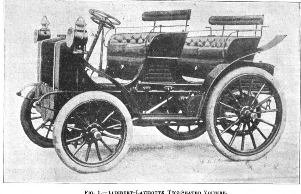
By 1900, the automobile had ceased to be merely a motor attached to a carriage, yet its mechanical architecture was far from settled. Manufacturers were still experimenting with chassis construction, steering systems, gear selection, cooling and lubrication, and the controls of one machine might differ radically from those of another. An exceptionally detailed article published in the American journal The Horseless Age on 15 August 1900 offers an opportunity to examine this formative period through the design of a car built by Audibert & Lavirotte of Monplaisir, Lyon. Entitled "The Audibert-Lavirotte Two-Seated Voiture," the report occupies three pages and is accompanied by seven illustrations showing the automobile, its chassis, steering mechanism, belt drive and gearbox. It is more than an exhibition notice: it describes how the principal components were constructed, operated and maintained.[1]
The American periodical acknowledged that its account was based on a recent description in the French journal La France Automobile. It is therefore a contemporary technical report derived from another publication, not the record of an independently conducted American road test. That distinction is important. The text contains substantial mechanical detail, but it also repeats some manufacturers' claims and leaves certain dimensions and performance figures unspecified. Read critically, it remains one of the most revealing surviving descriptions of an Audibert & Lavirotte automobile.
A Tubular Chassis Built Like a Bridge
The foundation of the car was an unusually elaborate chassis built from steel tubes. Instead of relying on two relatively simple longitudinal members of angle or channel section, the designers used upper and lower tubular members connected by vertical struts and transverse ties. The Horseless Age compared the resulting arrangement with a built-up bridge girder. The comparison was not merely picturesque: by separating the upper and lower members and tying them together, the construction used the depth of the frame to resist bending while avoiding the weight of massive solid sections. The individual joints were brazed, not assembled with the bolts or rivets familiar from some other contemporary structures.[1]
Such a frame demanded accurate manufacture. Tube lengths, joint fit and alignment had to be controlled before heating and joining, for an error at one point could disturb the location of the bearings and moving shafts. The magazine explicitly recognised the higher cost of the method but regarded the stiffness and the accurate relative position of the bearings as sufficient justification. The design is an interesting early example of treating the motor-car chassis as an engineered load-bearing structure rather than a carriage underframe modified to accept machinery. It should not, however, be confused with a modern welded space frame: the materials, joints and loading conditions were those of 1900.
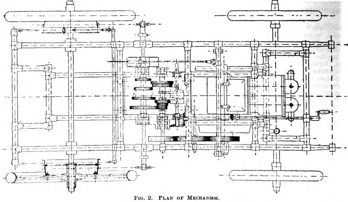
The overhead plan makes the organisation of the vehicle particularly clear. The horizontal engine was installed at the front, the change-speed and differential assemblies occupied the central part of the frame, and the final drive extended towards the rear wheels. This arrangement kept the main mechanical units within the perimeter of the chassis. The water tank, mounted in the front dash, was the principal component expressly described as attached to the body. Consequently, the makers could fit different styles of coachwork to the same mechanical frame. The journal called the body interchangeable, a useful commercial feature at a time when purchasers still specified their cars in the vocabulary of coachbuilding.
Suspension, Wheels and the Relationship Between Body and Frame
The suspension was almost as distinctive as the frame. At the front, two semi-elliptic leaf springs separated the axle from the chassis. At the rear, however, the manufacturer employed three springs: two longitudinal springs, one on each side, and a third transverse spring beneath the rear extremity of the frame. The transverse spring was fixed at its centre to the chassis and suspended at its ends from the rear extremities of the longitudinal members. The magazine praised the combination for the ease of the ride, although it furnished no measured comparisons with competing arrangements.[1]
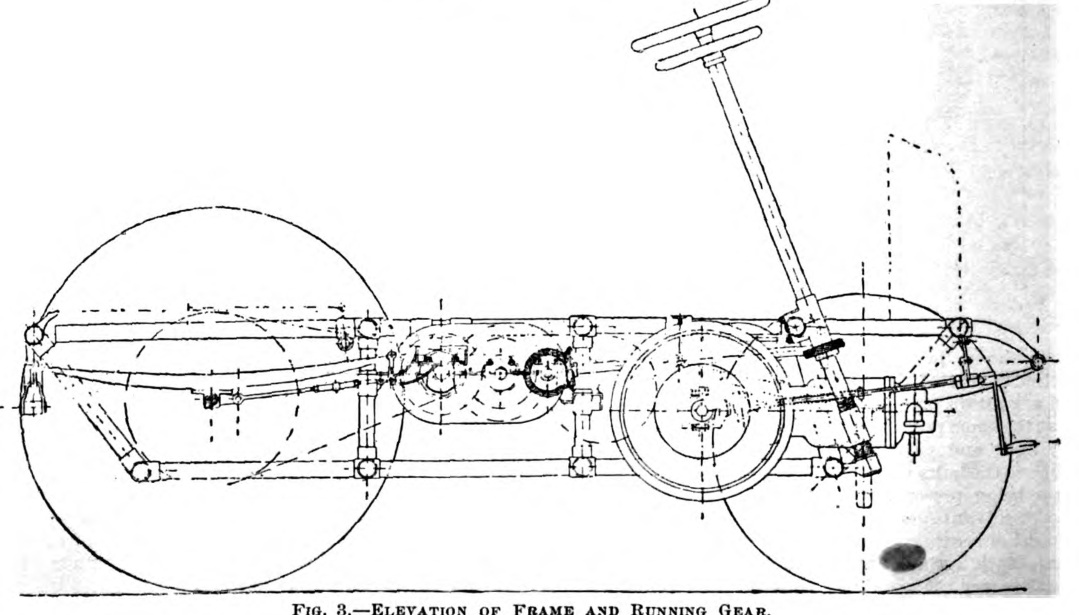
The side elevation shows the long, relatively low mechanical frame, the disposition of the wheels and the markedly inclined steering column. The account mentions bronze axle-boxes and notes that the spokes of the rear wheels were reinforced where the sprocket wheels were attached. This detail is significant because the sprockets formed part of the final-drive arrangement: torque had to be transferred into the wheel structure without imposing excessive local stresses on slender wooden spokes. The drawings and description indicate a chain final drive, although the report does not specify every dimension or give chain ratios. What appears visually to be a fairly conventional early touring car therefore concealed an intricate combination of tubular framing, springing and transmission.
The Horizontal Engine: Two Cylinders, or Four for Greater Power
The engine lay horizontally in the forward part of the chassis. According to the 1900 description, two-cylinder units were supplied for ratings up to 16 horsepower, while more powerful versions employed four cylinders. The article does not give bore, stroke, displacement, compression ratio or measured output for the particular vehicle illustrated. It would therefore be misleading to assign a precise engine capacity or power rating to the photograph solely on the strength of this account. The essential point is the manufacturer's adoption of a horizontally arranged engine as an integral element of a purpose-built front-engined chassis, rather than an auxiliary mechanism placed under a carriage seat.
A centrifugal governor regulated the admission of combustible mixture. The regulating mechanism was installed within one of the flywheels and protected by an aluminium cover. The driver could progressively reduce the governor's intervention by operating a separate accelerator beneath the steering wheel, increasing the engine's speed. This was not yet the familiar modern combination of an accelerator pedal and a fully standardised throttle linkage. It was instead a control system in which automatic regulation and direct driver intervention were deliberately combined. The manufacturer offered either electric-spark ignition or hot-tube ignition according to preference, another reminder that even the methods of initiating combustion were not yet universally standardised.[1]
The engine was also designed with particular attention to access for inspection and repairs. The account describes inlet-valve assemblies secured by straps and a single fastening bolt, removal of which exposed the inlet and exhaust valves. A dust-proof crankcase housed the camshaft, the two-to-one timing gears and associated rollers, and a hinged cover allowed access to the mechanism. These details deserve emphasis. Early motoring involved frequent attention to valve seating, ignition and lubrication, often far from an adequately equipped workshop. Ease of dismantling was therefore a practical requirement rather than a secondary convenience.
For starting, a relief cam held the exhaust valves open during the first half of the compression stroke. The aim was to reduce resistance while the engine was being turned over, an important consideration when starting depended on muscular effort rather than an electric starter. The period writer considered this arrangement superior to ordinary compression-relief cocks. That judgement expresses a contemporary preference; the extract provides neither comparative tests nor details sufficient to establish how widely the improvement was adopted.
Water Cooling Without a Pump
Another notable feature was the cooling system. The water tank occupied an elevated position at the front of the vehicle and contained numerous radiating tubes. The report states that circulation between engine and tank was maintained without a pump, relying on natural movement of the water. In modern terms the arrangement may be understood as a form of thermosyphon circulation, in which temperature-related density differences and the relative heights of the components sustain flow. The contemporary author described the effect more simply in terms of gravity; the surviving account does not include a complete cooling-system diagram.
Cooling water entered the jackets at the exhaust-valve boxes, where the highest local temperatures were likely to occur. The intention was to protect the valves and their seats against overheating, thereby reducing the need for repeated attention during long journeys. The magazine repeated a claim that the vehicle could travel 300 miles without replenishing the water supply. This was a statement about the supposed endurance of the cooling-water charge, not the fuel range of the automobile, and no independent trial establishing the figure is reported. The distinction matters because the design combined an inherently simple circulation system with a substantial claim for long-distance serviceability.
The Belt Drive and an Important Discrepancy in the Source
From the engine, power passed to an intermediate shaft carrying the change-speed mechanism. Here the article contains an unusually explicit documentary inconsistency. Its general arrangement drawing appears to show a toothed connection between the engine shaft and the intermediate shaft, yet the accompanying French description specifies a belt drive. The American writer drew attention to the discrepancy and pointed to the separate belt-transmission illustration as supporting the written account. Rather than silently resolving the matter, we should preserve the contemporary uncertainty: the published plan and the stated transmission arrangement do not agree in every detail.[1]
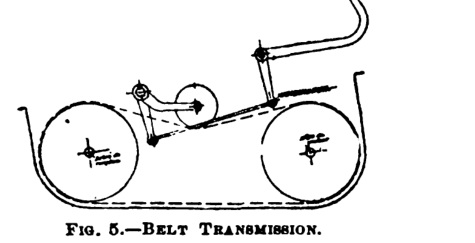
The belt arrangement shown in Figure 5 employed a movable jockey pulley pressing against the back of the belt. The driver applied the pulley by means of a foot pedal. Increasing belt tension enabled the mechanism to transmit power and thereby start the vehicle; varying the pulley's position also compensated for gradual stretching or contraction of the belt. This device performed part of the functional role later associated with a clutch, although it should not be described as a conventional friction-disc clutch. Its operation depended on controlled belt tension and contact, with the characteristic possibilities of belt slip and wear.
Two Handwheels: Steering and Gear Selection
Perhaps the most memorable feature of the Audibert & Lavirotte was the use of two concentric handwheels mounted on the steering column. The upper wheel steered the car through a screw mechanism acting on the front wheels. The inclined steering column was supported at two points near its lower end, making the assembly stiff; its working components were described as forged and tempered steel. The journal also observed what appeared to be an enclosed spring, termed a boîte à ressort, in one of the steering links. It interpreted this as a means of reducing stresses associated with the relatively irreversible action of the screw steering mechanism. Significantly, the American author presented the interpretation as an observation from the drawing, not a feature confirmed by the French description.
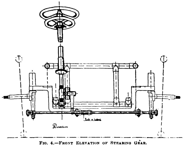
The second, lower handwheel was not for steering. It operated the change-speed mechanism. Rotation of this wheel was transmitted down a concentric tube to a spiral gear, which drove another gear connected to a longitudinal control shaft. Bevel gears transferred the motion to the shaft of a grooved cam drum acting upon the gearbox selectors. In this arrangement, choosing a gear was a controlled mechanical operation rather than the direct movement of a lever into an exposed gate. The arrangement was unusual, but it was by no means a mere curiosity: its designers were seeking a precise method of positioning the selector mechanism while allowing the driver to maintain a familiar hand position.
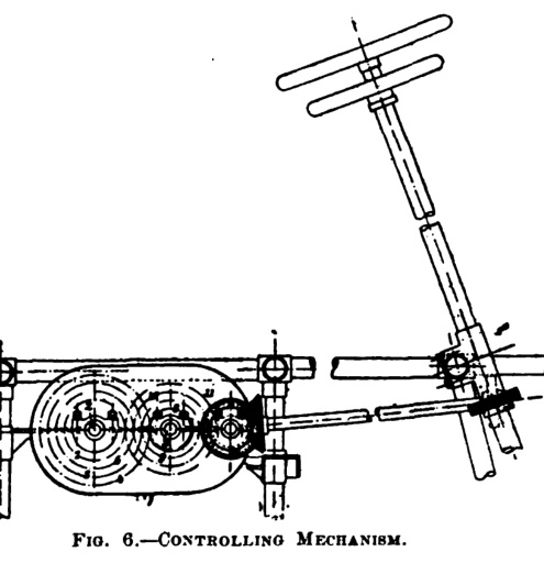
Figure 6 is especially useful because it isolates the controlling gear train, showing how the second handwheel could actuate the mechanism at a distance from the gearbox itself. The magazine states that the cam-grooved drum allowed the driver to select reverse directly from the high-speed position without passing through the intermediate selections. This describes the path taken by the selector mechanism; it is not evidence that reverse was meant to be engaged while the vehicle was travelling forward. Neither the presence of a modern synchromesh system nor the safe performance of such a manoeuvre can be inferred from the drawings.
An Enclosed Gearbox with Nickel-Steel Gears
The change-speed gears, the reversing train and the differential were contained in a dust-proof aluminium housing filled with oil. The shafts ran in bronze bearings lined with anti-friction metal; supplementary oil wells and rings were fitted to improve lubrication. All the gears were described as being made from nickel steel. Those associated with the differential shaft were machined integrally with the adjacent half of the differential drum and its sleeve, a costly arrangement intended to combine strength with reduced weight. It is striking how much attention was directed towards lubrication, sealing and bearing alignment at a time when exposed gears and vulnerable transmissions were still encountered on road vehicles.[1]
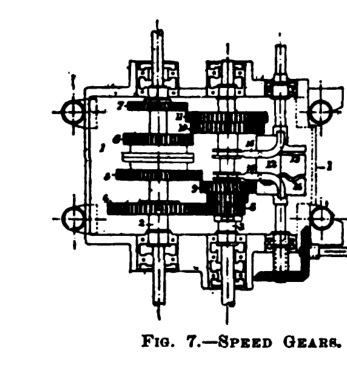
The report even discussed repair after gear-tooth failure. Its proposed solution was to machine away the damaged toothed rim while retaining the central web, then fasten a replacement rim to that web with rivets. This should be understood as a provision or suggested repair method, not as evidence that the procedure was routinely carried out. It illustrates the priorities of the designers: major components should be sufficiently robust for hard service yet, where possible, repairable without replacing the entire assembly. The exact number of forward ratios and their numerical gear ratios are not given in these three pages; Figure 7 documents the construction of the gear train, not a complete performance specification.
Braking and the Hazards of Early Roads
The car was equipped with two distinct braking arrangements. Band brakes acting on the rear wheels were operated by a hand lever positioned to the driver's right. A second brake acting on the differential shaft was controlled by a pedal beneath the right foot. According to the period description, the shaft brake was the one ordinarily used, while the wheel brakes were reserved chiefly for long descents. The relative emphasis may appear unfamiliar to a modern driver, but it must be read in the context of early driveline layouts and road conditions. Braking force applied to a transmission shaft passes through additional mechanical components before reaching the road wheels, while wheel brakes act more directly at the hubs.
The account also refers to a supplementary safety prop intended to guard against danger when climbing hills. Unfortunately, the brief description does not establish its detailed construction or exactly how it was deployed. It would be tempting to identify it as a particular form of anti-rollback device, but the document alone is insufficient to settle that question. What is beyond doubt is that hill-climbing and descending were major concerns in 1900, and safety depended on several mechanical expedients rather than a single standard braking system.
What the Seven Illustrations—and the Text—Actually Prove
The article is valuable precisely because it permits a close reading of the engineering rather than an assessment based only on the automobile's outward appearance. Figure 1 records the body and general arrangement; Figures 2 and 3 establish the relationship between frame, engine and running gear; Figure 4 shows the steering system; Figure 5 depicts the belt drive; Figure 6 explains the remote gear-selection control; and Figure 7 gives a direct view of the enclosed speed gears. Together they document a relatively advanced, purpose-built vehicle, with considerable attention to frame stiffness, driver controls, lubrication and maintainability.
They do not, however, establish everything one might wish to know. The specific car's bore, stroke, weight, road speed, fuel consumption and price are not stated. The text does not report a measured road test, and its assertion about cooling-water endurance remains an attributed claim. Most importantly, the plan of the engine-to-intermediate-shaft drive conflicts with the prose describing a belt. Preserving these limitations is more useful to an automotive historian than converting every statement into an unqualified fact. Even the title "two-seated voiture" is best retained as the journal's period terminology rather than interpreted as a reliable modern statement of passenger capacity.
Within those limits, the 1900 Audibert & Lavirotte deserves more than a passing mention in histories of early French motoring. Its brazed tubular chassis, unusual rear springing, dual-handwheel controls, carefully enclosed gearbox, nickel-steel gearing, natural-circulation cooling and attention to maintenance illustrate the breadth of experimentation undertaken by relatively small manufacturers before automobile architecture became standardised. The short life of the company should not obscure the quality of the technical questions its engineers were asking. For a few years at Monplaisir, Maurice Audibert and Émile Lavirotte participated directly in the transformation of the horseless carriage into the modern motor car.
Historical Sources
1. "The Audibert-Lavirotte Two-Seated Voiture," The Horseless Age, Vol. 6, No. 20, 15 August 1900, pp. 17–19, seven illustrations. Contemporary technical account adapted from a report in La France Automobile. All technical details discussed above derive from this three-page article unless otherwise indicated. Original pages from the author's archival collection.
2. Society of Automotive Historians in Britain, "Snapshot 7: 1900 Audibert et Lavirotte." Supplementary historical commentary on the marque and its unusual two-handwheel control arrangement. Historical article.
Illustrations: All seven figures are reproduced from the original publication in The Horseless Age, 15 August 1900. The historical drawings have not been redrawn or reconstructed.