
MAURICE AUDIBERT’S AUTOMATIC ENGINE-POSITIONING MECHANISM OF 1897
During the pioneering years of the automobile, starting a petrol engine was often a demanding mechanical operation. Before electric starting systems became available, motorists depended upon manual effort, carefully adjusted ignition and the correct positioning of the engine’s moving parts. A four-stroke internal-combustion engine presented a particular difficulty: although the crankshaft completed two revolutions during each working cycle, only one of the four piston strokes produced useful power. For a successful start, the engine had to be brought into a suitable position from which the combustible charge could be ignited and the cycle resumed.
In August 1897, the French automobile journal La Locomotion Automobile published an illustrated account of an invention by Maurice Audibert, co-founder of the Lyon automobile manufacturing firm Audibert & Lavirotte. Entitled Un perfectionnement des moteurs à pétrole par M. Audibert, the article described a recently patented mechanical arrangement intended to stop an engine automatically in the correct position for its subsequent restart. Although the publication occupied less than a page, the accompanying drawing reveals an ingenious combination of gears, a cam, connecting levers and a flywheel locking mechanism. The device illustrates the attention early automobile engineers devoted not merely to obtaining power from an engine, but to making it practical to operate.[1]
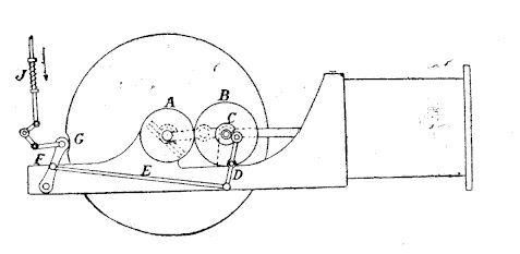
Original illustration from La Locomotion Automobile,
No. 34, 26 August 1897, p. 393.
The Starting Problem of the Four-Stroke Engine
To understand the purpose of Audibert’s invention, it is necessary to consider the operating cycle of a conventional four-stroke petrol engine. During the first stroke, the piston draws a combustible mixture into the cylinder through the inlet valve. During the second, the mixture is compressed. Ignition initiates the third, or power stroke, when the expanding gases exert pressure upon the piston and transmit mechanical energy through the connecting rod to the crankshaft. The fourth stroke expels the combustion products through the exhaust valve. The complete sequence therefore requires four piston strokes, corresponding to two full revolutions of the crankshaft.
In an engine without an electric starting motor, the operator had to supply the initial movement required to establish this sequence. The flywheel could be turned by hand or through a starting mechanism, but the crankshaft position and the phase of the four-stroke cycle were not necessarily convenient for obtaining an immediate firing impulse. The same angular position of the crankshaft recurs once during each revolution, whereas the corresponding phase of the complete four-stroke cycle recurs only after two revolutions. Consequently, crankshaft position alone does not identify whether the cylinder is approaching compression or the corresponding position in another part of the cycle.
The contemporary article explained this difficulty in practical terms. To prepare an engine for departure, the driver might have to manipulate the flywheel in order to bring the piston into a suitable starting position. Audibert proposed eliminating this preliminary operation by making the engine stop automatically at a predetermined point. The object was not to provide the energy required for starting, but to reduce the amount of manual preparation needed before the next attempt.
Audibert’s Mechanical Arrangement
The drawing published in La Locomotion Automobile represents a horizontal petrol engine equipped with a flywheel and an auxiliary stopping mechanism. The components are identified by letters, allowing the operation to be reconstructed from the brief French description. A small pinion, marked A, is driven by the engine and meshes with a larger gear, B, whose diameter is twice that of the driving pinion. Gear B is mounted on a shaft supported by the engine frame. A cam, C, is keyed to this shaft and acts through two levers, D and E, upon a pawl or catch designated F. The catch interacts with a notch, G, formed in the circumference of the engine flywheel.[1]
The purpose of the notch is to provide a definite mechanical stopping position. When the pawl enters it, further rotation of the flywheel is prevented, bringing the crankshaft to the predetermined angle. Yet the position of the notch is only one aspect of the invention. If the flywheel were fitted with an ordinary stationary catch, the mechanism could attempt to arrest the crankshaft every revolution, without distinguishing the two different phases of a four-stroke cycle. Audibert’s additional gear and cam mechanism was intended to overcome this problem by introducing a relationship between flywheel position and engine-cycle timing.
During normal operation the catch is held clear of the rotating flywheel. The article refers to a separate release device, or déclic, which the driver operates when preparing to stop the engine. This ensures that the stopping pawl does not remain engaged with the flywheel throughout ordinary running. The auxiliary levers and cam then govern the interaction between the catch and the flywheel notch as the engine approaches its selected resting position.
Why the Two-to-One Gear Ratio Matters
The most significant detail in the arrangement is the relationship between gears A and B. Since gear B has twice the diameter of gear A, the driven shaft turns at half the speed of the engine shaft, assuming the gears have the same tooth pitch. In other words, gear B and the cam attached to it complete one revolution for every two revolutions of the crankshaft. This is precisely the relationship required to follow the full cycle of a four-stroke engine.
The principle was already familiar in the operation of valve timing mechanisms. In an ordinary four-stroke engine, the camshaft must operate at half crankshaft speed so that the inlet and exhaust valves open at the correct intervals during the two-revolution cycle. Audibert applied the same basic timing relationship to a different function: the selection of an appropriate position at which the engine could be brought to rest.
The flywheel notch G returns to the same angular position during every crankshaft revolution. The cam C, however, returns to a corresponding position only after two crankshaft revolutions. By acting through levers D and E to lift or release the pawl F, the cam provides a means of distinguishing between successive appearances of the notch. In principle, this allows the stopping mechanism to be coordinated with a particular phase of the four-stroke cycle, rather than simply with an arbitrary crankshaft angle.
This timing relationship is the essential engineering idea behind the invention. The drawing does not supply all the dimensions, cam profiles or angular settings required for a complete kinematic reconstruction, so the exact sequence of pawl movement cannot be established in every detail. Nevertheless, the combination of the two-to-one reduction, the cam and the flywheel catch demonstrates how Audibert intended to link the stopping position to the engine’s operating cycle. It was a mechanical solution to what might otherwise have required the driver to judge piston position and valve timing manually.
Stopping the Engine and Preparing for Restarting
The mechanism was designed to remain inactive while the engine was running. When the driver wished to stop, the retaining device was released, permitting the pawl to cooperate with the cam mechanism and the notch in the flywheel. As the engine lost speed, the system was intended to bring the rotating assembly to rest at the position predetermined by the design. The driver would then be spared the separate task of turning the flywheel back to the necessary starting position.
One detail of the flywheel notch deserves particular attention. The French description specifies that the notch G was formed with a gentle slope, or pente douce. Its shape was intended to allow the pawl to escape when the first explosion caused the engine to rotate again. Thus, the locking arrangement was not conceived as a permanent rigid stop: it had to hold the flywheel in the desired resting position while also permitting the mechanism to disengage when the engine resumed operation.[1]
The inclined surface would have reduced the abruptness of this disengagement, but its exact effect depended on the geometry of the pawl, the contact forces and the torque delivered to the flywheel. The publication does not provide measurements of those parameters. In particular, the illustration does not establish whether the pawl could safely engage at an appreciable rotational speed or how the resulting stopping shock was controlled. These questions would have been important in any practical installation.
It is also necessary to distinguish positioning the crankshaft from actually starting the engine. Audibert’s device was not an electric starter, a compressed-air starter or an independent source of driving torque. It did not eliminate the need to provide an initial impulse, nor does the description explain how the combustible charge and ignition conditions were established or maintained for a subsequent start. The contemporary writer assumed that the selected stopping position would facilitate the process, but the effectiveness of the complete starting procedure is not demonstrated by the drawing alone.
Application to Other Engine Arrangements
The final paragraph of the 1897 article suggests that the device might be applied even more readily to engines in which the cylinder itself revolved, completing one revolution for every two revolutions of the flywheel. This observation extends the proposed principle beyond the horizontal engine selected for the accompanying illustration. It shows that the author regarded the relationship between the rotation of the engine components and the timing of the working cycle as more important than the particular disposition of the cylinder.
The remark is intriguing but incomplete. The article does not identify a specific manufacturer or give a second diagram showing how the mechanism would be adapted to such an engine. It should therefore be understood as a proposed application rather than evidence that an alternative version was constructed or installed. Even so, it illustrates an important characteristic of early automotive engineering: inventors frequently conceived their mechanisms as general solutions capable of adaptation to several different types of internal-combustion engine.
Practical Limitations and the Question of Adoption
The account describes Audibert’s improvement as recently patented, but does not provide a patent number, filing date or detailed specification. Without independently examining the corresponding patent, it would be premature to associate this particular mechanism with any of the other inventions registered in Maurice Audibert’s name. Nor does the newspaper notice establish whether a working prototype was tested, whether the device entered regular production or whether it was fitted to vehicles sold by Audibert & Lavirotte.
The mechanism also raises several practical questions that the period description does not answer. The energy remaining in the rotating flywheel as the engine slowed would have to be absorbed when the stopping pawl engaged. Repeated contact between the pawl and the notch could cause local wear, while variations in speed, lubrication and adjustment might affect the precision of the engagement. The cam timing would have to remain correctly synchronised with the engine cycle. These considerations are engineering implications of the proposed arrangement, not reported defects established by contemporary tests.
From a historical perspective, such limitations do not diminish the interest of the invention. They reveal the complexity of apparently elementary requirements that modern motorists take for granted. At the end of the nineteenth century, engineers had not yet converged on a standard combination of ignition controls, starting apparatus and operating procedures. A mechanical device that automatically positioned the engine for its next start therefore addressed a genuine difficulty encountered in early motor-car operation.
Maurice Audibert and the Search for Practical Engineering Solutions
The automatic stopping mechanism belongs to the same experimental engineering culture that shaped the automobiles produced at the Audibert & Lavirotte works in Monplaisir. Maurice Audibert was not concerned exclusively with assembling vehicles or reproducing established designs. His inventions addressed the mechanisms by which engines could be controlled, maintained and operated. The 1897 device is a particularly clear example because it attempts to solve a practical problem through the coordinated action of a reduction gear, a cam and a mechanical locking arrangement.
Three years later, the American journal The Horseless Age published a detailed technical description of an Audibert & Lavirotte automobile equipped with a tubular chassis, a horizontal engine, a belt transmission and an unusual gearbox controlled by a second handwheel beneath the steering wheel. That later account also emphasised accessibility, mechanical control and the practical requirements of operation. The two publications are evidence of sustained technical experimentation within the same manufacturing enterprise, although they do not establish that the 1897 stopping mechanism formed part of the automobile illustrated in 1900.[2]
The special interest of Audibert’s 1897 invention lies in the way it translated the timing of a four-stroke engine into a mechanical action performed for the benefit of the driver. The two-to-one gearing synchronised the auxiliary cam with the complete engine cycle; the cam and levers controlled the pawl; and the flywheel notch established the intended resting position. Whether or not the arrangement proved commercially successful, it illustrates the inventive effort required to transform the early petrol engine from a difficult experimental machine into an increasingly manageable source of motive power. Such mechanisms, many of them subsequently abandoned or superseded, form an essential part of the history of automobile engineering.
Historical Sources and References
1. G. D., “Un perfectionnement des moteurs à pétrole par M. Audibert,” La Locomotion Automobile, quatrième année, no. 34, 26 August 1897, p. 393. Contemporary illustrated description of the automatic engine-positioning mechanism. Original publication digitised by the Conservatoire national des arts et métiers (CNAM), Paris. Consult the original issue and table of contents.
2. “The Audibert-Lavirotte Two-Seated Voiture,” The Horseless Age, vol. 6, no. 20, 15 August 1900, pp. 17–19. Contemporary technical examination of the manufacturer’s chassis, engine, steering and transmission. See also The Audibert & Lavirotte Automobile of 1900: Engine, Chassis and Transmission, BrassCarEra.
Historical illustration: The original engine-stopping mechanism, with components A–G and the driver’s release catch, was published in La Locomotion Automobile, no. 34, 26 August 1897, p. 393. The diagram should be reproduced from the original archival page without alteration or reconstruction.